Topology
Use this screen to view the connections between Nebula Devices in the site. Click Site-wide > Topology to access this screen.
Site-wide > Topology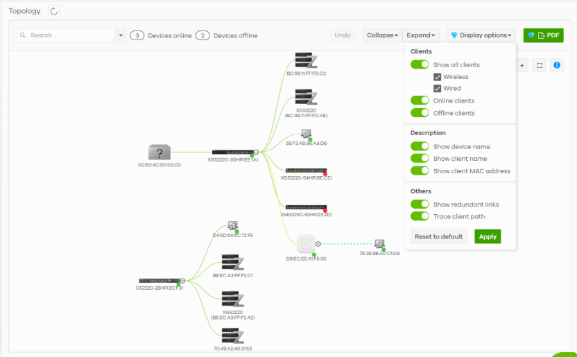
The icon of a node in the network topology indicates its Nebula Device type and the color shows whether the Nebula Device is online (green), has alerts (amber), or is offline (red). Stacking is a set of Nebula Switches that behaves as a single Nebula Switch. External Zyxel device is a device manufactured by Zyxel but not registered at the NCC or unable to work in Nebula cloud management mode. The client devices are classified according to it’s operating system. Other (?) means that NCC failed to identify the connected device (not a Zyxel Device) or identify the client device’s operating system.
The color of the connecting line shows the type of connection between 2 Nebula Devices, or the connection between a Nebula Device and a client device:
• Solid green line: this shows a wired (Ethernet cable) connection
• solid yellow line: this shows a PoE (Power over Ethernet) connection
• solid blue line: this shows a link aggregation (trunking) connection between Switches and Security Firewalls
• dotted blue line: this shows a WiFi connection
• dotted black line: this shows an active and backup (redundant) connection, or
• dotted green line: this shows a WiFi connection in a Mesh network.
Scroll the mouse up/down to zoom in/out, or click + / – for clearer viewing. Click and hold the left mouse button while moving the mouse to change the position of the network topology diagram. Click the Center icon ( ) to move the network topology diagram to the default position.
) to move the network topology diagram to the default position. Client devices must support LLDP in order to appear correctly after a Nebula accessory.
The following table describes the labels in this screen.
Label | Description |
|---|---|
(  ) ) | Click the Refresh icon to update this screen. |
Search | Set the filter to view the particular Nebula Device(s), client device(s), and VLAN ID in the network topology diagram. The number of matches is displayed, including the number of online/offline device(s). VLAN filtering criteria includes the following: • All Nebula Device interface configured with a corresponding VLAN ID. LAN, LAN1, and LAN2 are regarded as VLAN1. • Nebula APs (access points and wireless bridge) / Switches ports with a corresponding PVID (port VLAN ID). • Nebula APs / Switches having ports configured with allowed VLAN IDs. ‘All’ is regarded as matching any VLAN. • Nebula APs / Security Appliances broadcasting SSIDs configured with a corresponding VLAN ID. • Client devices belonging to a particular VLAN. |
Undo | Click this to cancel your action on the Collapse and Expand buttons. |
Collapse | Click this button and select All to hide all connections after the Security Appliance in the network topology diagram. 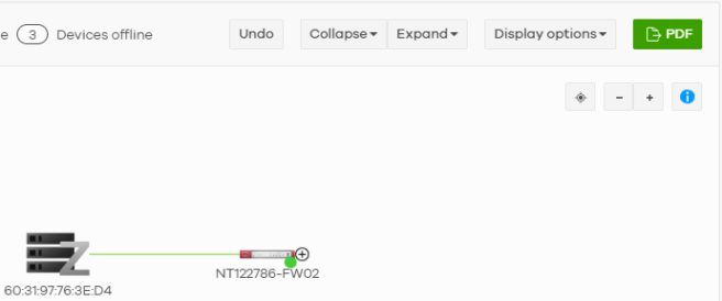 Alternatively, select All access points to hide all connections after the access point(s) in the network topology diagram. 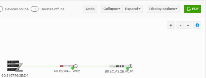 |
Expand | Click this button and select All to show all connections after the Security Appliance in the network topology diagram. 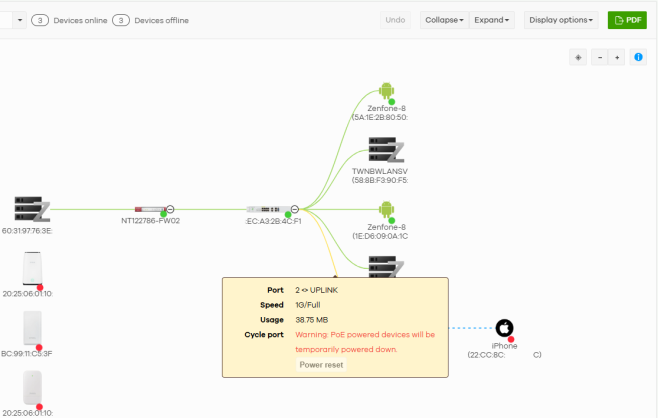 Alternatively, select All access points to show all connections after the access point(s) in the network topology diagram. |
Display options | Enable Show all clients > Wireless/Wired to display the WiFi/wired client(s) that are connected to your network. Enable Online clients / Offline clients to display all client(s) that are connected to the Nebula Device / disconnected from the Nebula Device. Enable Show device name / Show client name / Show client MAC address to show the Nebula Device information, such as MAC address / device name and/or client device’s MAC address / name in the network topology diagram. NCC only displays clients connected to your network from the last 2 hours.Enable Show redundant links to display the secondary connection between two nodes, and also display the Nebula Device(s) that are connected to your network but cannot be identified by the NCC. The non-Nebula Device(s) installed in the network are detected by the NCC through LLDP packets. if any. Enable Trace client path to display the connection path from the filtered client or device on the topology to the leftmost device, including the device on the WAN side of the Nebula Security Appliance. Then, click Apply. NCC remembers the display options for each site and applies them the next time the administrator visits the Topology page. |
PDF | Click this button to download the network topology diagram as a PDF file. |
(  / /  ) ) | Click these buttons to switch to vertical view or horizontal view. |
(  ) ) | Click this button to move the network topology diagram to the default position. |
(– / +) | Click these buttons to zoom in or zoom out for clearer viewing. |
(  / /  ) ) | Click the (  ) button to maximize the viewing space and enter full screen view. Click the ( ) button to maximize the viewing space and enter full screen view. Click the ( ) button or the Esc key to exit full screen view. ) button or the Esc key to exit full screen view. |
General
Click a Nebula Device node to view detailed Nebula Device information in the General tab. Click a client device node to view detailed client device information based on analytics gathered from the Site-wide > Clients pages. In the General tab, you can do the following:
• Click the edit icon beside the Nebula Device name to change the name of the Nebula Device.
• View the percentage of the Nebula Device’s processing capability that is currently being used in CPU usage.
• View the percentage of the Nebula Device’s RAM processing capability that is currently being used in Memory usage.
• Click Firmware status to update the Nebula Device’s firmware if it is not the latest.
• Click Locate to turn on the LOCATOR LED on the Nebula Device for 5 minutes. This shows the actual location of the Nebula Device in the topology.
• Specify the Port number and click Establish using Remote access to establish a remote connection to this Nebula Device.
• Click Reboot to restart the Nebula Device.
• View the percentage and value (Watts) of PoE power usage and the Total power the Nebula Device (Switches only) can provide to the connected PDs in PoE Power.
• View the WAN Usage of the Nebula Device (Security Appliances only). The y-axis shows the transmission speed of data sent or received through the WAN connection in megabits per second (Mbps). The x-axis shows the time period over which the traffic flow occurred.
Site-wide > Topology > General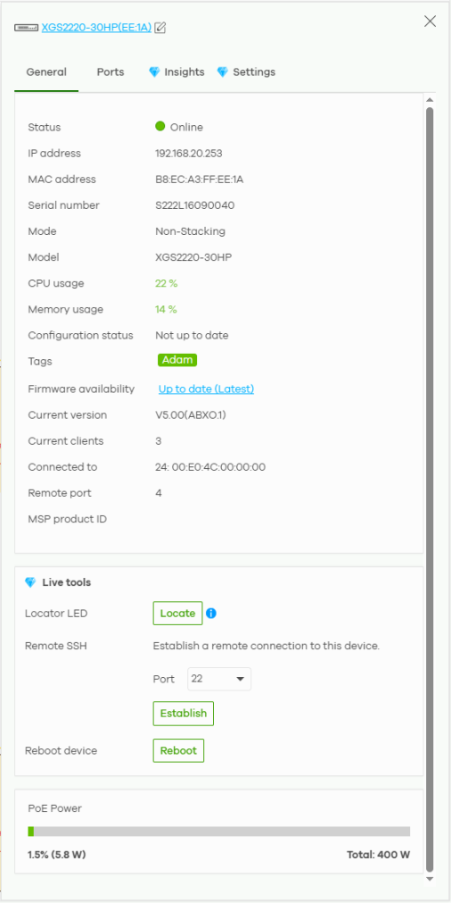
Ports
Click the Ports tab and move the pointer over a port to view the Nebula Device’s port details, such as Name, Status, LLDP, Type and Speed. If the port is supplying power to a node using Power over Ethernet (PoE), you can click Power reset to perform a power cycle on the port. This action temporarily disables PoE and then re-enables it, in order to reboot connected PoE devices. Click LLDP to go to the Site-wide > Devices > Access points > Details screen. See Access Point Details for more information. Click Configure ports to go to the Site-wide > Devices > (Nebula Device) page. See Site-wide > Devices > Switches: Switch Details for more information.
The Ports tab is not available for broadband routers and access points.Site-wide > Topology > Ports 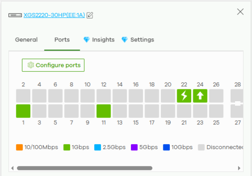
Insights
Click the Insights tab to view Nebula Device log messages for the past hour. Click View all to go to the Site-wide > Monitor > (Nebula Device) > Event log page to view more log messages. See Event Log for more information.
The Insights tab is not available for broadband routers.Site-wide > Topology > Insights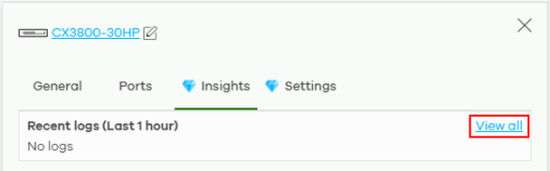
Settings
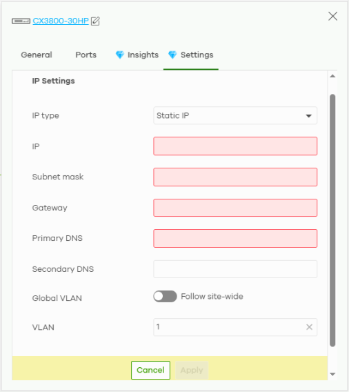
Click the Settings tab to change the IP type/address, subnet mask, gateway, primary DNS, VLAN setting. See Site-wide > Devices > Access points: Details for more information.
The Settings tab is only available for Access Points and Switches. To prevent an IP address conflict, NCC will prevent input of an IP address already used by another Nebula Device in the same site. When the Global VLAN: Follow site-wide configuration is enabled, it will use the site-wide management VLAN ID.
When the Global VLAN: Follow site-wide configuration is disabled, the Nebula Device’s management VLAN will use its individual VLAN settings rather than the site-wide management VLAN ID.
When the Global VLAN: Follow site-wide configuration is disabled, the Nebula Device’s management VLAN will use its individual VLAN settings rather than the site-wide management VLAN ID.
Site-wide > Topology > Settings