PoE Setup
PoE Status (for PoE models only)
 The following screens are available for the PoE models only.
The PoE models supports the IEEE 802.3bt High Power over Ethernet (PoE) standard.
A powered device (PD) is a device such as an access point or a switch, that supports PoE (Power over Ethernet) so that it can receive power from another device through an Ethernet port.
In the figure below, the IP camera and IP phone get their power directly from the Switch. Aside from minimizing the need for cables and wires, PoE removes the hassle of trying to find a nearby electric outlet to power up devices.
Powered Device Examples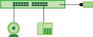
You can also set priorities so that the Switch is able to reserve and allocate power to certain PDs.
The PoE (Power over Ethernet) devices that supply or receive power and their connected Ethernet cables must all be completely indoors.PORT > PoE Setup > PoE Status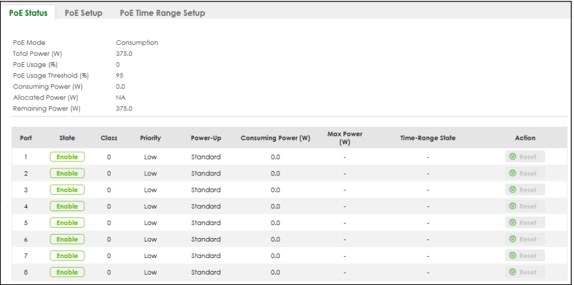
The following table describes the labels in this screen.
label | description |
|---|---|
PoE Mode | This field displays the power management mode used by the Switch, whether it is in Classification or Consumption mode. |
Total Power (W) | This field displays the total power the Switch can provide to the connected PoE-enabled devices on the PoE ports. |
PoE Usage (%) | This field displays the amount of power currently being supplied to connected PoE devices (PDs) as a percentage of the total PoE power the Switch can supply. When PoE usage reaches 100%, the Switch will shut down PDs one-by-one according to the PD priority which you configured in PORT > PoE Setup > PoE Setup. |
PoE Usage Threshold (%) | This field displays the percentage of PoE usage. The Switch will generate a trap and/or a log when the usage exceeds the specified threshold. |
Consuming Power (W) | This field displays the amount of power the Switch is currently supplying to the connected PoE-enabled devices. |
Allocated Power (W) | This field displays the total amount of power the Switch (in classification mode) has reserved for PoE after negotiating with the connected PoE devices. It shows NA when the Switch is in consumption mode. Consuming Power (W) can be less than or equal but not more than the Allocated Power (W). |
Remaining Power (W) | This field displays the amount of power the Switch can still provide for PoE. |
Port | This is the port index number. |
State | This field shows which ports can receive power from the Switch. • Disable – The PD connected to this port cannot get power supply. • Enable – The PD connected to this port can receive power. |
Class | This shows the power classification of the PD. Each PD has a specified maximum power that fall under one of the classes. The Class is a number from 0 to 8, where each value represents the range of power that the Switch provides to the PD. The power ranges in PoE standards are as follows. • Class 0 – default: 0.44 W to 15.4 W. • Class 1 – default: 0.44 W to 4 W. • Class 2 – default: 0.44 W to 7 W. • Class 3 – default: 0.44 W to 15.4 W. • Class 4 – default: 0.44 W to 30 W. • Class 5 – default: 0.45 W to 45 W. • Class 6 – default: 0.45 W to 60 W. You can extend or set a limit on the maximum power the connected PD can use on a port in PORT > PoE Setup > PoE Setup. |
Priority | When the total power requested by the PDs exceeds the total PoE power budget on the Switch, you can set the priority to allow the Switch to provide power to ports with higher priority first. • Critical has the highest priority. • High has the Switch assign power to the port after all critical priority ports are served. • Low has the Switch assign power to the port after all critical and high priority ports are served. |
Power-Up | This field displays the PoE setting the Switch uses to provide power on this port. |
Consuming Power (W) | This field displays the current amount of power consumed by the PD from the Switch on this port. |
Max Power (W) | This field displays the maximum amount of power the PD could use from the Switch on this port. This field displays “–” if the maximum power is not specified in PORT > PoE Setup > PoE Setup. |
Time-Range State | This field shows whether or not the port currently receives power from the Switch according to its schedule. • It shows “In” followed by the time range name if PoE is currently enabled on the port. • It shows “Out” if PoE is currently disabled on the port. • It shows “–” if no schedule is applied to the port. PoE is enabled by default. |
Action | Click Reset to perform a power cycle on the port currently supplying PoE power to the connected PoE-enabled device. |
PoE Setup
Use this screen to set the PoE power management mode, priority levels, power-up mode and the maximum amount of power for the connected PDs.
Click the PoE Setup tab in the PORT > PoE Setup screen. The following screen opens.
PORT > PoE Setup > PoE Setup 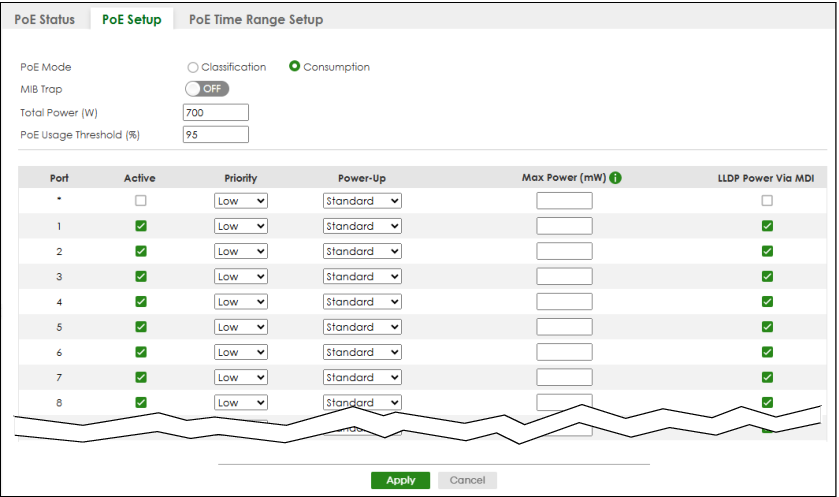
The following table describes the labels in this screen.
label | description |
|---|---|
PoE Mode | Select the power management mode you want the Switch to use. • Classification – Select this if you want the Switch to reserve the maximum power for each PD according to the PD’s power class and priority level. If the total power supply runs out, PDs with lower priority do not get power to function. In this mode, the maximum power is reserved based on what you configure in Max Power or the standard power limit for each class. • Consumption – Select this if you want the Switch to supply the actual power that the PD needs. The Switch also allocates power based on a port’s Max Power and the PD’s power class and priority level. The Switch puts a limit on the maximum amount of power the PD can request and use. In this mode, the default maximum power that can be delivered to the PD is 30 W (IEEE 802.3at Class 4) or 22 W (IEEE 802.3af Classes 0 to 3). |
MIB Trap | The Switch sends traps (monitoring event notification) to an SNMP (Simple Network Management Protocol) manager when an event occurs. Select ON to allow sending of MIB Trap when the following situations occur: • Situation 1 – Trap sent whenever a PoE port status change occurs (PoE port delivers power or delivers no power to a PD (powered device) • Situation 2 – Trap sent in cases where the total power usage exceeds the PoE usage threshold • Situation 3 – Trap sent if total usage power decreases below the PoE usage threshold (only if previous total power usage exceeded the PoE usage threshold and a trap was sent). If the MIB Trap is ON, you must also configure:• SNMP trap destination (SYSTEM > SNMP > SNMP), SNMP trap group (SYSTEM > SNMP > SNMP Trap Group) and SNMP trap port (SYSTEM > SNMP > SNMP Trap Port) for Situation 1 • SNMP trap destination and SNMP trap group for Situation 2 and Situation 3. See Section 25.1 on page 192 for more information on configuring SNMP. |
Total Power (W) | By default, this field displays the total power the Switch can provide to the connected PoE-enabled devices on the PoE ports. • XMG2230-28HP: 700 W (default). Enter a number ranging from 1 to 1440 W to set the maximum PoE power the PD(s) could use from this Switch. • XMG2230-52HP: 960 W (default). Enter a number ranging from 1 to 2400 W to set the maximum PoE power the PD(s) could use from this Switch. This field is only for configuration when the Switch is powered up by DC power. |
PoE Usage Threshold (%) | Enter a number ranging from 1 to 99 to set the threshold. The Switch will generate a trap and/or log when the actual PoE usage is higher than the specified threshold. |
Port | This is the port index number. |
* | Settings in this row apply to all ports. Use this row only if you want to make some settings the same for all ports. Use this row first to set the common settings and then make adjustments on a port-by-port basis. Changes in this row are copied to all the ports as soon as you make them. |
Active | Select this to provide power to a PD connected to the port. If left unchecked, the PD connected to the port cannot receive power from the Switch. |
Priority | When the total power requested by the PDs exceeds the total PoE power budget on the Switch, you can set the PD priority to allow the Switch to provide power to ports with higher priority. Select Critical to give the highest PD priority on the port. Select High to set the Switch to assign the remaining power to the port after all critical priority ports are served. Select Low to set the Switch to assign the remaining power to the port after all critical and high priority ports are served. |
Power-Up | Set how the Switch provides power to a connected PD at power-up. Standard – the Switch follows the IEEE 802.3 Power over Ethernet standard to supply power to the connected PDs during power-up. Compatible – the Switch provides PD with power on the port without performing PoE classification. Select this if the connected PD does not comply with any PoE standard. When you change the Power-Up mode, you need to do any of the following: • Click Reset on the Action field of the port supplying PoE power to the connected PD in PORT > PoE Setup > PoE Status, or • Disconnect and reconnect the Ethernet cable supplying PoE power from the port to the connected PD. |
Max Power (mW) | Specify the maximum amount of power the PD could use from the Switch on this port. If you leave this field blank, the Switch refers to the standard or default maximum power for each class. The setting you enter here is only valid when the power-up mode is set to Compatible. |
LLDP Power Via MDI | Select this to have the Switch negotiate PoE power with the PD connected to the port by transmitting LLDP Power Via MDI TLV frames. This helps the Switch allocate less power to the PD on this port. The connected PD must be able to request PoE power through LLDP. The Power Via MDI TLV allows PoE devices to advertise and discover the MDI power support capabilities of the sending port on the remote device. • Port Class • MDI Supported • MDI Enabled • Pair Controllable • PSE Power Pairs • Power Class |
Apply | Click Apply to save your changes to the Switch’s run-time memory. The Switch loses these changes if it is turned off or loses power, so use the Save link on the top navigation panel to save your changes to the non-volatile memory when you are done configuring. |
Cancel | Click Cancel to begin configuring this screen afresh. |
PoE Time Range Setup
Use this screen to apply a schedule to the ports on the Switch. You must first configure a schedule in the SYSTEM > Time Range > Time Range screen.
Click the PoE Time Range Setup tab in the PORT > PoE Setup screen. The following screen opens.
PORT > PoE Setup > PoE Time Range Setup (Standalone Mode)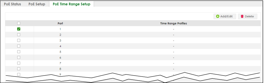
The following table describes the labels in this screen.
label | description |
|---|---|
Port | This field displays the index number of the port. Click a port number to change the schedule settings. |
Time Range Profiles | This field displays the name of the schedule which is applied to the port. PoE is enabled at the specified time or date. |
Select an entry’s checkbox to select a specific entry. Otherwise, select the checkbox in the table heading row to select all entries. | |
Add/Edit | Click Add/Edit to add a new rule or edit a selected one. |
Delete | Check the rules that you want to remove and then click the Delete button. |
Add/Edit PoE Time Range
To access this screen, click the Add/Edit button or select an entry from the list and click the Add/Edit button.
PORT > PoE Setup > PoE Time Range Setup > Add/Edit (Standalone Mode)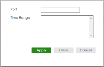
The following table describes the labels in this screen.
label | description |
|---|---|
Port | Enter the number of the port to which you want to apply a schedule. |
Time Range | This field displays the name of the schedule that you have created using the SYSTEM > Time Range > Time Range screen. Select a pre-defined schedule to control when the Switch enables PoE to provide power on the port. To select more than one schedule, press [SHIFT] and select the choices at the same time. |
Apply | Click Apply to save your changes to the Switch’s run-time memory. The Switch loses these changes if it is turned off or loses power, so use the Save link on the top navigation panel to save your changes to the non-volatile memory when you are done configuring. |
Clear | Click Clear to clear the fields to the factory defaults. |
Cancel | Click Cancel to not save the configuration you make and return to the last screen. |