ARP Inspection
ARP Inspection Status
Use this screen to look at the current list of MAC address filters that were created because the Switch identified an unauthorized ARP packet. When the Switch identifies an unauthorized ARP packet, it automatically creates a MAC address filter to block traffic from the source MAC address and source VLAN ID of the unauthorized ARP packet. To open this screen, click SECURITY > IPv4 Source Guard > ARP Inspection > ARP Insp. Status.
SECURITY > IPv4 Source Guard > ARP Inspection > ARP Insp. Status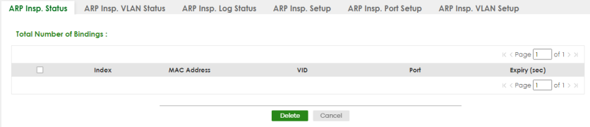
The following table describes the labels in this screen.
label | description |
|---|---|
Total Number of Bindings | This field displays the current number of MAC address filters that were created because the Switch identified unauthorized ARP packets. |
Index | This field displays a sequential number for each MAC address filter. |
MAC Address | This field displays the source MAC address in the MAC address filter. |
VID | This field displays the source VLAN ID in the MAC address filter. |
Port | This field displays the source port of the discarded ARP packet. |
Expiry (sec) | This field displays how long (in seconds) the MAC address filter remains in the Switch. You can also delete the record manually (Delete). |
Select an entry’s checkbox to select a specific entry. Otherwise, select the checkbox in the table heading row to select all entries. | |
Delete | Click this to remove the selected entries. |
Cancel | Click this to clear the Delete checkboxes above. |
ARP Inspection VLAN Status
Use this screen to look at various statistics about ARP packets in each VLAN. To open this screen, click SECURITY > IPv4 Source Guard > ARP Inspection > ARP Insp. VLAN Status.
SECURITY > IPv4 Source Guard > ARP Inspection > ARP Insp. VLAN Status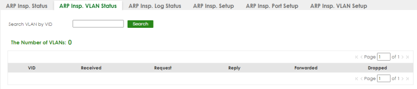
The following table describes the labels in this screen.
label | description |
|---|---|
Search VLAN by VID | Specify the VLANs you want to view in the section below. Use a comma (,) to separate individual VLANs or a hyphen (-) to indicates a range of VLANs. For example, “3,4” or “3-9”. |
Search | Click this to display the specified range of VLANs in the section below. |
The Number of VLANs | This is the number of VLANs that match the searching criteria and display in the list below. The number displays when you use the Search button to look for certain VLANs. The default value is 0. |
VID | This field displays the VLAN ID of each VLAN in the range specified above. |
Received | This field displays the total number of ARP packets received from the VLAN since the Switch last restarted. |
Request | This field displays the total number of ARP Request packets received from the VLAN since the Switch last restarted. |
Reply | This field displays the total number of ARP Reply packets received from the VLAN since the Switch last restarted. |
Forwarded | This field displays the total number of ARP packets the Switch forwarded for the VLAN since the Switch last restarted. |
Dropped | This field displays the total number of ARP packets the Switch discarded for the VLAN since the Switch last restarted. |
ARP Inspection Log Status
Use this screen to look at log messages that were generated by ARP packets and that have not been sent to the syslog server yet. To open this screen, click SECURITY > IPv4 Source Guard > ARP Inspection > ARP Insp. Log Status.
SECURITY > IPv4 Source Guard > ARP Inspection > ARP Insp. Log Status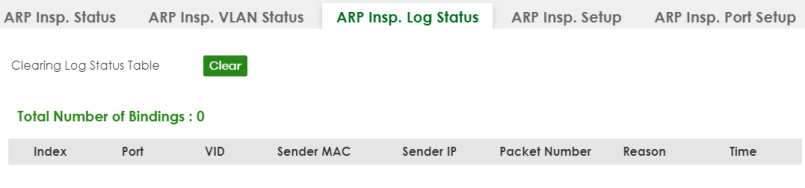
The following table describes the labels in this screen.
label | description |
|---|---|
Clearing Log Status Table | Click Clear to remove all the log messages that were generated by ARP packets and that have not been sent to the syslog server yet. |
Total number of Bindings | This field displays the number of log messages that were generated by ARP packets and that have not been sent to the syslog server yet. If one or more log messages are dropped due to unavailable buffer, there is an entry called overflow with the current number of dropped log messages. |
Index | This field displays a sequential number for each log message. |
Port | This field displays the source port of the ARP packet. |
VID | This field displays the source VLAN ID of the ARP packet. |
Sender MAC | This field displays the source MAC address of the ARP packet. |
Sender IP | This field displays the source IP address of the ARP packet. |
Packet Number | This field displays the number of ARP packets that were consolidated into this log message. The Switch consolidates identical log messages generated by ARP packets in the log consolidation interval into one log message. You can configure this interval in the SECURITY > IPv4 Source Guard > ARP Inspection > ARP Insp. Setup screen. |
Reason | This field displays the reason the log message was generated. dhcp deny: An ARP packet was discarded because it violated a dynamic binding with the same MAC address and VLAN ID. static deny: An ARP packet was discarded because it violated a static binding with the same MAC address and VLAN ID. deny: An ARP packet was discarded because there were no bindings with the same MAC address and VLAN ID. dhcp permit: An ARP packet was forwarded because it matched a dynamic binding. static permit: An ARP packet was forwarded because it matched a static binding. In the SECURITY > IPv4 Source Guard > ARP Inspection > ARP Insp. VLAN Setup screen, you can configure the Switch to generate log messages when ARP packets are discarded or forwarded based on the VLAN ID of the ARP packet. |
Time | This field displays when the log message was generated. |
ARP Inspection Setup
Use this screen to enable ARP inspection on the Switch. You can also configure the length of time the Switch stores records of discarded ARP packets and global settings for the ARP inspection log. To open this screen, click SECURITY > IPv4 Source Guard > ARP Inspection > ARP Insp. Setup.
SECURITY > IPv4 Source Guard > ARP Inspection > ARP Insp. Setup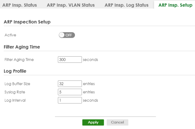
The following table describes the labels in this screen.
label | description |
|---|---|
ARP Inspection Setup | |
Active | Enable the switch button to enable ARP inspection on the Switch. You still have to enable ARP inspection on specific VLAN and specify trusted ports. |
Filter Aging Time | |
Filter Aging Time | This setting has no effect on existing MAC address filters. Enter how long (1 – 2147483647 seconds) the MAC address filter remains in the Switch after the Switch identifies an unauthorized ARP packet. The Switch automatically deletes the MAC address filter afterwards. Type 0 if you want the MAC address filter to be permanent. |
Log Profile | |
Log Buffer Size | Enter the maximum number (1 – 1024) of log messages that were generated by ARP packets and have not been sent to the syslog server yet. Make sure this number is appropriate for the specified Syslog Rate and Log Interval. If the number of log messages in the Switch exceeds this number, the Switch stops recording log messages and simply starts counting the number of entries that were dropped due to unavailable buffer. Click Clearing Log Status Table in the SECURITY > IPv4 Source Guard > ARP Inspection > ARP Insp. Log Status screen to clear the log and reset this counter. |
Syslog Rate | Type the maximum number of syslog messages the Switch can send to the syslog server in one batch. This number is expressed as a rate because the batch frequency is determined by the Log Interval. You must configure the syslog server to use this. Enter 0 if you do not want the Switch to send log messages generated by ARP packets to the syslog server. The relationship between Syslog Rate and Log Interval is illustrated in the following examples: • Four invalid ARP packets per second, Syslog Rate is 5, Log Interval is 1: the Switch sends 4 syslog messages every second. • Six invalid ARP packets per second, Syslog Rate is 5, Log Interval is 2: the Switch sends 5 syslog messages every 2 seconds. |
Log interval | Type how often (1 – 86400 seconds) the Switch sends a batch of syslog messages to the syslog server. Enter 0 if you want the Switch to send syslog messages immediately. See Syslog Rate for an example of the relationship between Syslog Rate and Log Interval. |
Apply | Click Apply to save your changes to the Switch’s run-time memory. The Switch loses these changes if it is turned off or loses power, so use the Save link on the top navigation panel to save your changes to the non-volatile memory when you are done configuring. |
Cancel | Click this to reset the values in this screen to their last-saved values. |
ARP Inspection Port Setup
Use this screen to specify whether ports are trusted or untrusted ports for ARP inspection. You can also specify the maximum rate at which the Switch receives ARP packets on each untrusted port. To open this screen, click SECURITY > IPv4 Source Guard > ARP Inspection > ARP Insp. Port Setup.
SECURITY > IPv4 Source Guard > ARP Inspection > ARP Insp. Port Setup (Standalone Mode)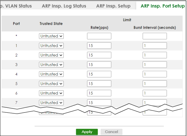
The following table describes the labels in this screen.
label | description |
|---|---|
Port | This field displays the port number. |
* | Settings in this row apply to all ports. Use this row only if you want to make some settings the same for all ports. Use this row first to set the common settings and then make adjustments on a port-by-port basis.  Changes in this row are copied to all the ports as soon as you make them. Changes in this row are copied to all the ports as soon as you make them. |
Trusted State | Select whether this port is a trusted port (Trusted) or an untrusted port (Untrusted). The Switch does not discard ARP packets on trusted ports for any reason. The Switch discards ARP packets on untrusted ports in the following situations: • The sender’s information in the ARP packet does not match any of the current bindings. • The rate at which ARP packets arrive is too high. You can specify the maximum rate at which ARP packets can arrive on untrusted ports. |
Limit | Rate and Burst Interval settings have no effect on trusted ports. |
Rate (pps) | Specify the maximum rate (1 – 2048 packets per second) at which the Switch receives ARP packets from each port. The Switch discards any additional ARP packets. Enter 0 to disable this limit. |
Burst Interval (seconds) | The burst interval is the length of time over which the rate of ARP packets is monitored for each port. For example, if the Rate is 15 pps and the burst interval is 1 second, then the Switch accepts a maximum of 15 ARP packets in every one-second interval. If the burst interval is 5 seconds, then the Switch accepts a maximum of 75 ARP packets in every five-second interval. Enter the length (1 – 15 seconds) of the burst interval. |
Apply | Click Apply to save your changes to the Switch’s run-time memory. The Switch loses these changes if it is turned off or loses power, so use the Save link on the top navigation panel to save your changes to the non-volatile memory when you are done configuring. |
Cancel | Click this to reset the values in this screen to their last-saved values. |
ARP Inspection VLAN Setup
Use this screen to enable ARP inspection on each VLAN and to specify when the Switch generates log messages for receiving ARP packets from each VLAN. To open this screen, click SECURITY > IPv4 Source Guard > ARP Inspection > ARP Insp. VLAN Setup.
SECURITY > IPv4 Source Guard > ARP Inspection > ARP Insp. VLAN Setup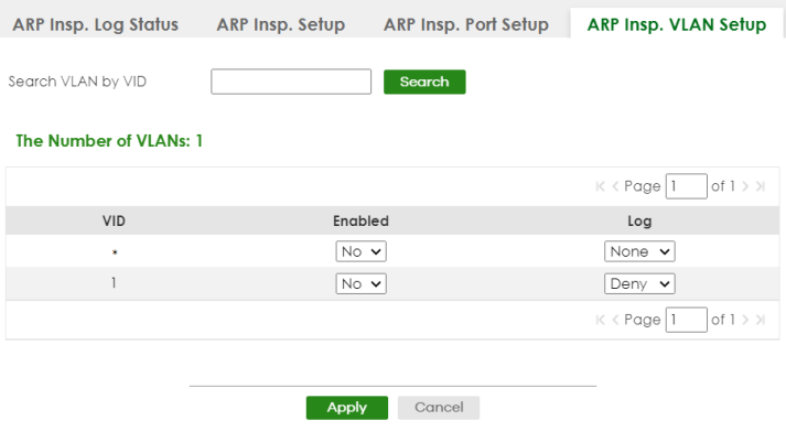
The following table describes the labels in this screen.
label | description |
|---|---|
Search VLAN by VID | Specify the VLANs you want to manage in the section below. Use a comma (,) to separate individual VLANs or a hyphen (-) to indicates a range of VLANs. For example, “3,4” or “3-9”. |
Search | Click this to display the specified range of VLANs in the section below. |
The Number of VLANs | This display the number of ARP inspection VLAN search results. |
VID | This field displays the VLAN ID of each VLAN in the range specified above. If you configure the * VLAN, the settings are applied to all VLANs. |
Enabled | Select Yes to enable ARP inspection on the VLAN. Select No to disable ARP inspection on the VLAN. |
Log | Specify when the Switch generates log messages for receiving ARP packets from the VLAN. None: The Switch does not generate any log messages when it receives an ARP packet from the VLAN. Deny: The Switch generates log messages when it discards an ARP packet from the VLAN. Permit: The Switch generates log messages when it forwards an ARP packet from the VLAN. All: The Switch generates log messages every time it receives an ARP packet from the VLAN. |
Apply | Click Apply to save your changes to the Switch’s run-time memory. The Switch loses these changes if it is turned off or loses power, so use the Save link on the top navigation panel to save your changes to the non-volatile memory when you are done configuring. |
Cancel | Click this to reset the values in this screen to their last-saved values. |
IPv6 Source Guard
The purpose of IPv6 source guard is to distinguish between authorized and unauthorized users by using a binding table that validates the source of IPv6 traffic. The binding table can be manually created or be learned through Dynamic Host Configuration Protocol version 6 snooping (DHCPv6 snooping). IPv6 source guard can deny IPv6 traffic from an unknown source. The IPv6 source guard binding table includes:
• IPv6 address
• IPv6 prefix
• VLAN ID
• Port number
• MAC address
Enable IPv6 source guard on a port for the Switch to check incoming IPv6 packets on that port. A packet is allowed when it matches any entry in the IPSG binding table. If a user tries to send IPv6 packets to the Switch that do not match an entry in the IPSG binding table, the Switch will drop these packets. The Switch forwards matching traffic normally. The IPv6 source guard related screens are available in standalone mode.
IPv6 Source Binding Status
Use this screen to look at the current IPv6 dynamic and static bindings and to remove dynamic bindings based on IPv6 address and/or IPv6 prefix. Bindings are used to distinguish between authorized and unauthorized packets in the network. The Switch learns the bindings by snooping DHCP packets (dynamic bindings) and from information provided manually by administrators (static bindings). To open this screen, click SECURITY > IPv6 Source Guard > IP Static Binding > IP Source Binding Status.
SECURITY > IPv6 Source Guard > IP Static Binding > IP Source Binding Status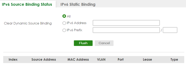
The following table describes the labels in this screen.
label | description |
|---|---|
Clear Dynamic Source Binding | Specify how you want the Switch to remove dynamic IPv6 source binding entries when you click Flush. • Select All to remove all of the dynamic entries from the IPv6 source binding table. • Select IPv6 Address and enter an IPv6 address to remove the dynamic entries snooped with the specified IPv6 address. • Select IPv6 Prefix and enter a Prefix address to remove the dynamic entries snooped with the specified Prefix address. |
Flush | Click this to remove dynamic IPv6 source binding entries according to your selections. |
Cancel | Click this to reset the values above based or if not applicable, to clear the fields above. |
Index | This field displays a sequential number for each binding. |
Source Address | This field displays the source IP address in the binding. If the entry is blank, this field will not be checked in the binding. |
MAC Address | This field displays the source MAC address in the binding. If the entry is blank, this field will not be checked in the binding. |
VLAN | This field displays the source VLAN ID in the binding. If the entry is blank, this field will not be checked in the binding. |
Port | This field displays the port number in the binding. If this field is blank, the binding applies to all ports. |
Lease | This field displays how many days, hours, minutes, and seconds the binding is valid; for example, 2d3h4m5s means the binding is still valid for 2 days, 3 hours, 4 minutes, and 5 seconds. This field displays infinity if the binding is always valid (for example, a static binding). |
Type | This field displays how the Switch learned the binding. S: This static binding was learned from information provided manually by an administrator. DH: This dhcp-snooping binding was learned by snooping DHCP packets. |
IPv6 Static Binding
Use this screen to view or configure an IPv6 source guard binding table entry and manage IPv6 static bindings. Static bindings are uniquely identified by the source IPv6 address / prefix. Each source IPv6 address / prefix can only be in one static binding. If you try to create a static binding with the same source IPv6 address / prefix as an existing static binding, the new static binding replaces the original one. To open this screen, click SECURITY > IPv6 Source Guard > IPv6 Static Binding > IPv6 Static Binding.
SECURITY > IPv6 Source Guard > IPv6 Static Binding > IPv6 Static Binding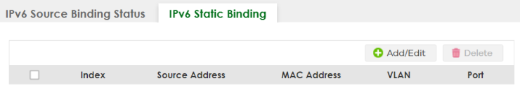
The following table describes the labels in this screen.
label | description |
|---|---|
Index | This field displays a sequential number for each binding. |
Source Address | This field displays the IPv6 address or IPv6 prefix and prefix length in the binding. |
MAC Address | This field displays the source MAC address in the binding. If the entry is blank, this field will not be checked in the binding. |
VLAN | This field displays the source VLAN ID in the binding. If the entry is blank, this field will not be checked in the binding. |
Port | This field displays the port number in the binding. If this field is blank, the binding applies to all ports. |
Select an entry’s checkbox to select a specific entry. Otherwise, select the checkbox in the table heading row to select all entries. | |
Add/Edit | Click Add/Edit to add a new entry or edit a selected one. |
Delete | Click Delete to remove the selected entries. |
Add/Edit IPv6 Static Binding
Use this screen to manually create an IPv6 source guard binding table entry and manage IPv6 static bindings. Click Add/Edit, or select an entry and click Add/Edit in the SECURITY > IPv6 Source Guard > IPv6 Static Binding > IPv6 Static Binding screen to display this screen.
SECURITY > IPv6 Source Guard > IPv6 Static Binding > IPv6 Static Binding > Add/Edit (Standalone Mode)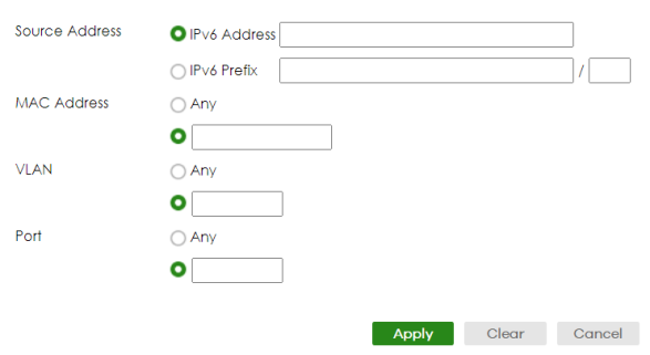
The following table describes the labels in this screen.
label | description |
|---|---|
Source Address | Enter the IPv6 Address or IPv6 Prefix and prefix length in the binding. |
MAC Address | Enter the source MAC address in the binding. If this binding does not check this field, select Any. You cannot choose Any for all three of MAC Address, VLAN and Port. You must fill in at least one. |
VLAN | Enter the source VLAN ID in the binding. If this binding does not check this field, select Any. |
Port | Specify the ports in the binding. If this binding has one port, select the first radio button and enter the port number in the field to the right. |
Apply | Click Apply to save your changes to the Switch’s run-time memory. The Switch loses these changes if it is turned off or loses power, so use the Save link on the top navigation panel to save your changes to the non-volatile memory when you are done configuring. |
Clear | Click Clear to clear the fields to the factory defaults. |
Cancel | Click Cancel to not save the configuration you make and return to the last screen. |
IPv6 Source Guard Policy
Use this screen to have IPv6 source guard forward valid IPv6 addresses and/or IPv6 prefixes that are stored in the binding table and allow or block data traffic from all link-local addresses. To open this screen, click SECURITY > IPv6 Source Guard > IPv6 Source Guard > IPv6 Source Guard Policy.
• If you select Validate Address and not Validate Prefix, traffic for a binding entry that matches a IPv6 address and VLAN ID, port number, and MAC address will be forwarded. If this binding entry is a IPv6 prefix, the traffic will be denied.
• If you select Validate Prefix and not Validate Address, traffic for a binding entry that matches a IPv6 prefix and VLAN ID, port number, and MAC address will be forwarded. If this binding entry is a IPv6 address, the traffic will be denied.
• If you select both Validate Prefix and Validate Address then traffic matching either IPv6 address or prefix will be forwarded.
SECURITY > IPv6 Source Guard > IPv6 Source Guard > IPv6 Source Guard Policy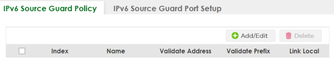
The following table describes the labels in this screen.
label | description |
|---|---|
Index | This field displays a sequential number for each policy. |
Name | This field displays the descriptive name for identification purposes for this IPv6 source guard policy. |
Validate Address | This field displays the Validate Address status for this IPv6 source guard policy. |
Validate Prefix | This field displays the Validate Prefix status for this IPv6 source guard policy. |
Link Local | This field displays the Link Local traffic status for this IPv6 source guard policy. |
Select an entry’s checkbox to select a specific entry. Otherwise, select the checkbox in the table heading row to select all entries. | |
Add/Edit | Click Add/Edit to add a new entry or edit a selected one. |
Delete | Click Delete to remove the selected entries. |
Add/Edit an IPv6 Source Guard Policy
Click Add/Edit, or select an entry and click Add/Edit in the SECURITY > IPv6 Source Guard > IPv6 Source Guard > IPv6 Source Guard Policy screen to display this screen.
SECURITY > IPv6 Source Guard > IPv6 Source Guard > IPv6 Source Guard Policy > Add/Edit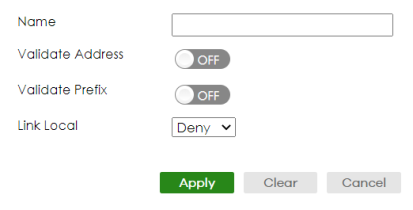
The following table describes the labels in this screen.
label | description |
|---|---|
Name | Enter a descriptive name for identification purposes for this IPv6 source guard policy. You can enter up to 32 printable ASCII characters except [ ? ], [ | ], [ ' ], [ " ], or [ , ]. |
Validate Address | Select Validate Address to have IPv6 source guard forward valid addresses that are stored in the binding table. |
Validate Prefix | Select Validate Prefix to have IPv6 source guard forward valid prefixes that are stored in the binding table. |
Link Local | Select Permit to allow data traffic from all link-local addresses; otherwise leave the setting at Deny. A link-local address is an IPv6 unicast address that can be automatically configured on any interface using the link-local prefix FE80::/10 and the interface identifier in the modified EUI-64 format. |
Apply | Click Apply to save your changes to the Switch’s run-time memory. The Switch loses these changes if it is turned off or loses power, so use the Save link on the top navigation panel to save your changes to the non-volatile memory when you are done configuring. |
Clear | Click Clear to clear the fields to the factory defaults. |
Cancel | Click Cancel to not save the configuration you make and return to the last screen. |
IPv6 Source Guard Port Setup
Use this screen to apply configured IPv6 source guard policies to ports you specify. Use port * to apply a policy to all ports. To open this screen, click SECURITY > IPv6 Source Guard > IPv6 Source Guard > IPv6 Source Guard Port Setup.
SECURITY > IPv6 Source Guard > IPv6 Source Guard > IPv6 Source Guard Port Setup (Standalone Mode)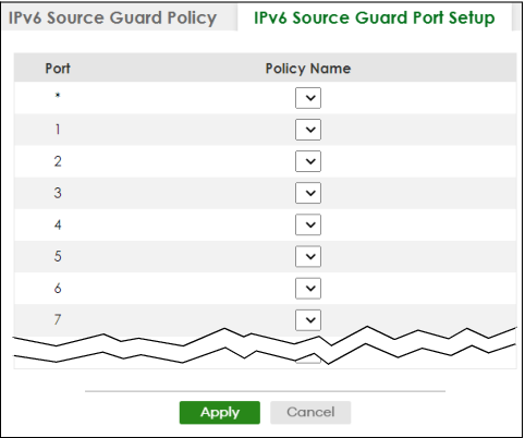
The following table describes the labels in this screen.
label | description |
|---|---|
Port | This field displays the port number. |
* | Settings in this row apply to all ports. Use this row only if you want to make some settings the same for all ports. Use this row first to set the common settings and then make adjustments on a port-by-port basis. Changes in this row are copied to all the ports as soon as you make them. |
Policy Name | Select an IPv6 source guard policy that the Switch will apply to this port. |
Apply | Click Apply to save your changes to the Switch’s run-time memory. The Switch loses these changes if it is turned off or loses power, so use the Save link on the top navigation panel to save your changes to the non-volatile memory when you are done configuring. |
Cancel | Click this to reset the values in this screen to their last-saved values. |
IPv6 Snooping Policy Setup
Use this screen to view and dynamically create an IPv6 source guard binding table using a DHCPv6 snooping policy. A DHCPv6 snooping policy lets the Switch sniff DHCPv6 packets sent from a DHCPv6 server to a DHCPv6 client when it is assigning an IPv6 address. When a DHCPv6 client successfully gets a valid IPv6 address, DHCPv6 snooping builds the binding table dynamically. To open this screen, click SECURITY > IPv6 Source Guard > IPv6 Snooping > IPv6 Snooping Policy Setup.
If you do not select Protocol and Prefix Glean, then the Switch cannot perform DHCPv6 snooping.SECURITY > IPv6 Source Guard > IPv6 Snooping > IPv6 Snooping Policy Setup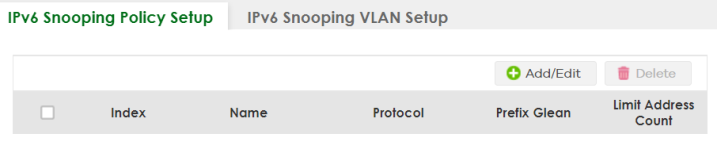
The following table describes the labels in this screen.
label | description |
|---|---|
Index | This field displays a sequential number for each IPv6 snooping policy. |
Name | This field displays the descriptive name for identification purposes for this IPv6 source guard policy. |
Protocol | This field displays the protocols learned from DHCPv6 sniffed packets. |
Prefix Glean | This field displays the IPv6 prefixes learned from DHCPv6 sniffed packets. |
Limit Address Count | This field displays the number of IPv6 addresses and prefixes learned using the IPv6 snooping policy. |
Select an entry’s checkbox to select a specific entry. Otherwise, select the checkbox in the table heading row to select all entries. | |
Add/Edit | Click Add/Edit to add a new entry or edit a selected one. |
Delete | Click Delete to remove the selected entries. |
Add/Edit a IPv6 Snooping Policy
Use this screen to dynamically create an IPv6 source guard binding table using a DHCPv6 snooping policy. Click Add/Edit, or select an entry and click Add/Edit in the SECURITY > IPv6 Source Guard > IPv6 Snooping > IPv6 Snooping Policy Setup screen to display this screen.
SECURITY > IPv6 Source Guard > IPv6 Snooping > IPv6 Snooping Policy Setup > Add/Edit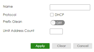
The following table describes the labels in this screen.
label | description |
|---|---|
Name | Enter a descriptive name for identification purposes for this IPv6 snooping policy. You can enter up to 32 printable ASCII characters except [ ? ], [ | ], [ ' ], [ " ], or [ , ]. |
Protocol | Select DHCP to let the Switch sniff DHCPv6 packets sent from a DHCPv6 server to a DHCPv6 client. |
Prefix Glean | Enable the switch button to learn the IPv6 prefix and length from DHCPv6 sniffed packets. |
Limit Address Count | This is the number of IPv6 addresses and prefixes learned using the IPv6 snooping policy. The maximum limit address count is the maximum size of the IPv6 source guard binding table. See the product data sheet for the latest specifications. |
Apply | Click Apply to save your changes to the Switch’s run-time memory. The Switch loses these changes if it is turned off or loses power, so use the Save link on the top navigation panel to save your changes to the non-volatile memory when you are done configuring. |
Clear | Click Clear to clear the fields to the factory defaults. |
Cancel | Click Cancel to not save the configuration you make and return to the last screen. |
IPv6 Snooping VLAN Setup
Use this screen to enable a DHCPv6 snooping policy on a specific VLAN interface. To open this screen, click SECURITY > IPv6 Source Guard > IPv6 Snooping > IPv6 Snooping VLAN Setup.
SECURITY > IPv6 Source Guard > IPv6 Snooping > IPv6 Snooping VLAN Setup
The following table describes the labels in this screen.
label | description |
|---|---|
Index | This field displays a sequential number for each binding. |
Interface | This field displays the VLAN interface. |
Policy | This field displays the DHCPv6 snooping policy. |
Select an entry’s checkbox to select a specific entry. Otherwise, select the checkbox in the table heading row to select all entries. | |
Add/Edit | Click Add/Edit to add a new entry or edit a selected one. |
Delete | Click Delete to remove the selected entries. |
Add/Edit an IPv6 Snooping VLAN
Use this screen to add/edit a DHCPv6 snooping policy on a specific VLAN interface. Click Add/Edit, or select an entry and click Add/Edit in the SECURITY > IPv6 Source Guard > IPv6 Snooping > IPv6 Snp. VLAN Setup screen to display this screen.
SECURITY > IPv6 Source Guard > IPv6 Snooping > IPv6 Snp. VLAN Setup > Add/Edit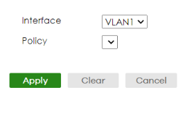
The following table describes the labels in this screen.
label | description |
|---|---|
Interface | Select the VLAN interface to apply the selected DHCPv6 snooping policy. |
Policy | Select the IPv6 snooping policy to apply to this VLAN interface. |
Apply | Click Apply to save your changes to the Switch’s run-time memory. The Switch loses these changes if it is turned off or loses power, so use the Save link on the top navigation panel to save your changes to the non-volatile memory when you are done configuring. |
Clear | Click Clear to clear the fields to the factory defaults. |
Cancel | Click Cancel to not save the configuration you make and return to the last screen. |
IPv6 DHCP Trust Setup
Use this screen to specify which ports are trusted for DHCPv6 snooping. To open this screen, click SECURITY > IPv6 Source Guard > DHCPv6 Trust Setup.
DHCPv6 solicit packets are sent from a DHCPv6 client to a DHCPv6 server. Reply packets from a DHCPv6 server connected to an untrusted port are discarded.Use port * to have all ports be Untrusted or Trusted.
SECURITY > IPv6 Source Guard > DHCPv6 Trust Setup (Standalone Mode)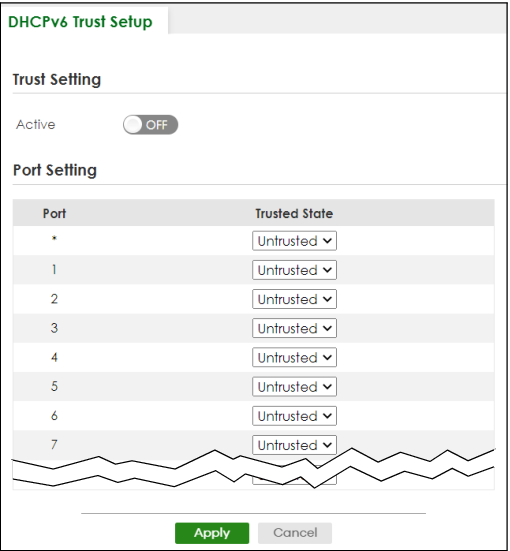
The following table describes the labels in this screen.
label | description |
|---|---|
Trust Setting | |
Active | Enable the switch button to specify whether ports are trusted or untrusted ports for DHCP snooping. If you do not select this then IPv6 DHCP Trust is not used and all ports are automatically trusted. |
Port Setting | |
Port | This field displays the port number. |
* | Settings in this row apply to all ports. Use this row only if you want to make some settings the same for all ports. Use this row first to set the common settings and then make adjustments on a port-by-port basis. Changes in this row are copied to all the ports as soon as you make them. |
Trusted State | Select whether this port is a trusted port (Trusted) or an untrusted port (Untrusted). Trusted ports are connected to DHCPv6 servers or other switches. Untrusted ports are connected to subscribers, and the Switch discards DHCPv6 packets from untrusted ports in the following situations: • The packet is a DHCPv6 server packet (for example, ADVERTISE, REPLY, or RELAY-REPLY). • The source MAC address and source IP address in the packet do not match any of the current bindings. |
Apply | Click Apply to save your changes to the Switch’s run-time memory. The Switch loses these changes if it is turned off or loses power, so use the Save link on the top navigation panel to save your changes to the non-volatile memory when you are done configuring. |
Cancel | Click this to reset the values in this screen to their last-saved values. |
Technical Reference
This section provides technical background information on the topics discussed in this chapter.
ARP Inspection Overview
Use ARP inspection to filter unauthorized ARP packets on the network. This can prevent many kinds of man-in-the-middle attacks, such as the one in the following example.
Example: Man-in-the-middle Attack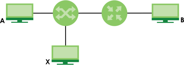
In this example, computer B tries to establish a connection with computer A. Computer X is in the same broadcast domain as computer A and intercepts the ARP request for computer A. Then, computer X does the following:
• It pretends to be computer A and responds to computer B.
• It pretends to be computer B and sends a message to computer A.
As a result, all the communication between computer A and computer B passes through computer X. Computer X can read and alter the information passed between them.
ARP Inspection and MAC Address Filters
When the Switch identifies an unauthorized ARP packet, it automatically creates a MAC address filter to block traffic from the source MAC address and source VLAN ID of the unauthorized ARP packet. You can configure how long the MAC address filter remains in the Switch.
These MAC address filters are different than regular MAC address filters.
• They are stored only in volatile memory.
• They do not use the same space in memory that regular MAC address filters use.
• They appear only in the ARP Inspection screens and commands, not in the MAC Address Filter screens and commands.
Trusted vs. Untrusted Ports
Every port is either a trusted port or an untrusted port for ARP inspection. This setting is independent of the trusted or untrusted setting for DHCP snooping. You can also specify the maximum rate at which the Switch receives ARP packets on untrusted ports.
The Switch does not discard ARP packets on trusted ports for any reason.
The Switch discards ARP packets on untrusted ports in the following situations:
• The sender’s information in the ARP packet does not match any of the current bindings.
• The rate at which ARP packets arrive is too high.
Syslog
The Switch can send syslog messages to the specified syslog server when it forwards or discards ARP packets. The Switch can consolidate log messages and send log messages in batches to make this mechanism more efficient.
Configuring ARP Inspection
Follow these steps to configure ARP inspection on the Switch.
1 Configure DHCP snooping.
It is recommended you enable DHCP snooping at least one day before you enable ARP inspection so that the Switch has enough time to build the binding table.2 Enable ARP inspection on each VLAN.
3 Configure trusted and untrusted ports, and specify the maximum number of ARP packets that each port can receive per second.