Getting Started
Getting Started Overview
This chapter shows you how to use the Zyxel Device’s various features.
• WiFi Network Setup - Choose the operation mode, set up a WiFi network, and optimize channel selection, transmit power and roaming.
• Limit Network Bandwidth for Each WiFi Client - Restrict the network bandwidth on a WiFi client.
• Network Security - Change the WiFi security, set up a RADIUS server, a rogue AP list, a friendly AP list, and a MAC filter list, and restrict users’ access on the network.
• Device Settings - Change the management IP address, the login password, and the system name.
• Device Management Using Nebula - Register the Zyxel Device through the NCC Portal or the Nebula Mobile App.
• Device Maintenance - Upgrade firmware, download and restore the device configuration.
• Collect Diagnostic Information - Collect diagnostic information to help troubleshoot system and network issues in standalone and cloud-managed modes. The diagnostic files include system, wireless, networking, authentication, cloud management, and other information for analysis.
• Remote Access to the Zyxel Device - Configure ways to access the Zyxel Device.
WiFi Network Setup
In this section, we show you how to:
Select the Operation Mode
The Zyxel Device has different Operation Modes (OP modes) to act as different roles in a network. You can select different OP modes for each radios. Not all OP modes are supported by all models. To select the OP mode, go to Configuration > Wireless > AP Management.
The Zyxel Device supports the following OP modes:
• Select AP Mode if you want WiFi clients to connect to the Zyxel Device.
• Select Root AP Mode if you want the Zyxel Device to wirelessly extend your WiFi network and also allow WiFi clients to connect to the Zyxel Device.
• Select Repeater Mode if you want the Zyxel Device to wirelessly extend your WiFi network (WDS).
Set Up Multiple WiFi Networks in AP Mode
To set up WiFi networks for WiFi clients in AP Mode, you need to first create a Radio Profile, Security Profile, and SSID profile. Each profile is described below.
Profile name | description |
|---|---|
Radio Profile | Determines how the Zyxel Device broadcasts the wireless signal. It defines wireless radio settings such as the frequency bands, channel, channel width, and transmit power. |
Security Profile | Defines the security policy for a WiFi network. It determines data encryption method and whether users must enter a password to connect to the WiFi network. |
SSID Profile | Defines the WiFi network (SSID) that users connect to. It defines settings such as the WiFi network (SSID) name, Security Profile, available frequency bands, and bandwidth limits. |
This tutorial uses the following scenario:
A small company wants to configure two WiFi networks, one for employees, and one for guests. Follow the steps below to configure the WiFi networks.
Configure the Radio Profile
The 2.4 GHz band provides wider coverage but slower speeds, while the 5 GHz band provides higher speeds but a smaller coverage area. Configure the WiFi networks to broadcast on both bands.
1 Go to Configuration > Object > AP Profile > Radio > Add. Create two radio profiles with the following parameters. Click OK.
Profile name | 802.11 Band |
|---|---|
Office_radio_24G | 2.4G |
Office_radio_5G | 5G |
Configure the Security Profile
In this example, the office does not use a RADIUS server for user authentication.
WPA2-MIX allows both WPA and WPA2 clients to connect to the same WiFi network. Configure two Security Profiles using wpa2-mix with Personal authentication:
• One for the employee WiFi network
• One for the guest WiFi network
Configure a different pre-shared key for each profile to prevent guests from accessing the employee WiFi network.
2 Go to Configuration > Object > AP Profile > SSID > Security List. Add or edit the security profiles using the following parameters.
profile name | security mode | personal pre-shared key |
|---|---|---|
Office_security | wpa2-mix | a1357911 |
Guest_security | wpa2-mix | b24681012 |
Configure the SSID Profile
In this example, the employee WiFi network uses both the 2.4 GHz and 5 GHz bands. The guest WiFi network uses only the 2.4 GHz band. Configure two SSID profiles to broadcast these networks and assign the Security Profiles created in the previous step to each SSID profile.
3 Go to Configuration > Object > AP Profile > SSID > SSID List. Add or edit the SSID profiles using the following parameters. Click OK.
profile name | SSID | Band | security profile |
|---|---|---|---|
Office_SSID | 2F_WiFi | 2.4G, 5G | Office_security |
Office_SSID_Guest | Guest_WiFi | 2.4G | Guest_security |
 The the name you enter in the SSID field is the WiFi network name that clients see when searching for available WiFi networks.
Configure AP Management
To broadcast the WiFi networks, assign the Radio Profiles and SSID Profiles created in the previous steps to the Zyxel Device.
4 Go to Configuration > Wireless > AP Management > WLAN Setting. Use the following parameters to configure Radio 1 and Radio 2.
radio OP mode | radio profile | ssid profile | |
|---|---|---|---|
Radio 1 | AP Mode | Office_radio_24G | Office_SSID |
Office_SSID_Guest | |||
radio 2 | AP Mode | Office_radio_5G | Office_SSID |
Verify the WiFi Connection
5 To see your current WiFi settings and check if the WiFi connection is up, go to Monitor > Wireless > AP Information.
6 If the WiFi connection is up, employees can search for the 2F_WiFi SSID and connect to the employee WiFi network. Guests can search for the Guest_WiFi SSID and connect to the guest WiFi network. When prompted, enter the Pre-Shared Key configured in the Security Profile.
Set Up a WiFi Network in Root AP/Repeater Mode
To wirelessly extend a WiFi network (WDS), you need two Zyxel Devices, one in Repeater mode and one in Root AP mode. You should already have the root AP set up.
The Zyxel Device in Root AP/Repeater mode cannot connect with other company’s APs.1 Go to Configuration > Object > WDS Profile in your root AP Web Configurator and click Add.
2 Enter a profile name, a WDS SSID, and a pre-shared key.
3 Go to Configuration > Wireless > AP Management, select the Radio WDS Profile of the radio on which you are setting the WDS connection to use the WDS profile you set, and click Apply.
4 Do steps 1 and 3 for the Zyxel Device in Repeater mode using the same WDS SSID and pre-shared key.
5 Once the security settings of the Zyxel Device in Root AP and Repeater modes match one another, the connection between the two Zyxel Devices is made.
If your Zyxel Device supports wireless bridging, you can extend a wired network from the port on the WiFi repeater, do the following steps:
6 Go to Configuration > Wireless > AP Management, select Setup WDS Wireless Bridging to enable WiFi bridge on the Zyxel Device in Repeater mode.
7 Connect the client device to the Zyxel Device’s LAN port with an Ethernet cable.
Make sure the VLAN settings on both the root AP and the WiFi repeater are exactly the same so they can communicate.When wireless bridge is enabled, WiFi interfaces for client devices will be disabled. You can only transmit data through the ports of the Zyxel Device in Repeater mode.To set up a WDS in APC-managed Zyxel Devices, see the ZyWALL ATP, USG FLEX, or NCC User’s Guide.
Set Up General and Guest WiFi Networks on Both Radios
The following example shows you how to create two WiFi networks (Zyxel_General and Zyxel_Guest) using the following settings for both Radio 1 (2.4 GHz) and Radio 2 (5 GHz). You should have already created two security profiles, Security_Profile1 and Security_Profile2, on the Configuration > Object > AP Profile > SSID > Security List screen. See Creating a Security Profile for a tutorial on creating security profiles.
For the Guest WiFi, enable Enable Intra-BSS Traffic blocking to prohibit Guest WiFi clients from directly connecting to each other. To separate the Guest WiFi network from the General internal WiFi network, create two VLANs, VLAN 10 and VLAN 20, on your firewall (F), such as ZyWALL. Set the General WiFi network to be in VLAN 10, where your internal network is. Set the Guest WiFi network to be in VLAN 20. This way, Guest WiFi clients will not be able to access the wired LAN network of the firewall (F) in VLAN 10 while still able to access the Internet.
General and Guest WiFi Networks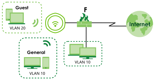
General | Guest | |
|---|---|---|
Profile Name | General | Guest |
SSID | Zyxel_General | Zyxel_Guest |
Band | 2.4 GHz/5 GHz | 2.4 GHz/5 GHz |
Security Profile | Security_Profile1 Security Mode: WPA3 Authentication: Personal Pre-Shared Key: zyxel1234 | Security_Profile2 Security Mode: WPA3 Authentication: Personal Pre-Shared Key: guest1234 |
VLAN ID | 10 | 20 |
Rate Limiting | 0 (unlimited) | Downlink: Up to 15 Mbps Uplink: Up to 10 Mbps |
Enable Intra-BSS Traffic Blocking | Disabled | Enabled |
Schedule SSID | No schedule | Monday-Friday: 09:00-17:00 |
1 Go to Configuration > Object > AP Profile > SSID > SSID List, click Add to create an SSID profile.
2 Configure the first SSID – Zyxel_General using the parameters given above, and then click OK.
3 Configure the second SSID – Zyxel_Guest using the parameters given above, and then click OK.
4 Go to Configuration > Wireless > AP Management. Click the first SSID Profile of Radio 1 (2.4 GHz). A drop-down list appears. Select the General SSID profile you just configured.
5 Click the second SSID Profile and select the Guest SSID profile.
6 Click the first SSID Profile of Radio 2 (5 GHz). A drop-down list appears. Select the General SSID profile you just configured. Click the second SSID Profile and select the Guest SSID profile.
7 Click Apply on the bottom of the screen. The General and Guest SSID profiles are now applied on Radio 1 and Radio 2. You should now be able to see the Zyxel_General and Zyxel_Guest SSIDs on your WiFi devices for both 2.4 GHz and 5 GHz radio bands. General WiFi users can access the Internet and your local network. Guest users can only access the Internet.
Optimize WiFi Settings for Clients
To optimize WiFi settings for clients, adjust channel selection, transmission power and roaming settings.
Optimize Channel Selection
Do the following to optimize channel selection:
Enable Dynamic Channel Selection (DCS)
Dynamic channel selection (DCS) automatically scans and selects for the channel with the least amount of interference and switches to it when necessary. For more information about DCS, see Dynamic Channel Selection (DCS). Configure DCS in one of the following management methods:
Standalone
Enable DCS for Each Radio
1 Log into the Web Configurator using your account name and password.
2 Go to Configuration > Object > AP Profile > Radio. Select the radio profile which you want to enable DCS.
3 The Edit Radio Profile screen appears. In General Settings, select DCS in Channel Selection. In the example below, Channel 52 is selected, and the DCS scan interval is set to 720 minutes. Click OK.
When the Zyxel Device is performing a Dynamic Channel Selection (DCS) scan, and selecting a Dynamic Frequency Selection (DFS) channel (CH52 ~ CH144) for its service channel, the Zyxel Device is currently conducting the Channel Availability Check (CAC). The process wait time is 10 minutes:
• For channels 120~128, the wait time is 10 minutes.
• For other DFS channels, the wait time is 1 minute.
During the process the Zyxel Device LED will blink in blue. When completed, the Zyxel Device LED will change.
Enable DCS for All Radios
1 Log into the Web Configurator using your account name and password.
2 Go to Configuration > Wireless > DCS, click DCS now for the immediate DCS scan. Then, click Apply.
Cloud Managed
If your Zyxel Device is registered in NCC and is operating in Cloud Managed Mode, follow the steps below. To register your Zyxel Device with NCC, see Device Management Using Nebula for step-by-step instructions.
1 Log into the NCC portal.
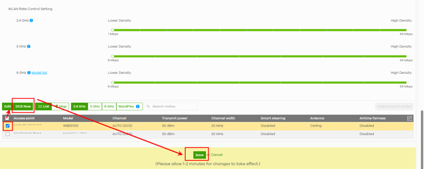
2 Go to Site-Wide > Configure > Access points > Radio settings.
Scroll down to the Access point list, select the checkbox for the Zyxel Device. Click DCS Now, and then click Save. See Enable DCS for Each Radio for the wait time of the process to complete.
Reduce Channel Width in High-Interference Environments
In high-interference environments, use a narrower channel width to reduce interference and improve overall network performance. The following table shows the recommended channel width for each band in different deployment scenarios:
number of Access points | RECOMMENDED channel width |
|---|---|
Single AP | 2.4 GHz: 20 MHz 5 GHz: 80 MHz 6 GHz: 320 MHz |
Low-density (2-5 APs) | 2.4 GHz: 20 MHz 5 GHz: 80 MHz 6 GHz: 160 MHz |
Moderate-density (6-9 APs) | 2.4 GHz: 20 MHz 5 GHz: 40 MHz 6 GHz: 160 MHz |
High-density (More than 10 APs) | 2.4 GHz: 20 MHz 5 GHz: 20 MHz 6 GHz: 80 MHz |
Configure the channel width in one of the following management methods:
Standalone
1 Log in to the Web Configurator using the admin account and password on the device label.
2 Go to Configuration > Object > AP Profile > Radio. Select the radio profile you want to configure, and then click the Edit icon. The below example uses the Wiz_Radio_5G radio profile to configure the channel width.
3 The Edit Radio Profile screen appears. In General Settings, select the recommended channel width from the Channel Width drop-down list for the 5 GHz radio profile, according to the Suggested Channel Width table above. Click OK.
Cloud Managed
1 Log in to the NCC portal.
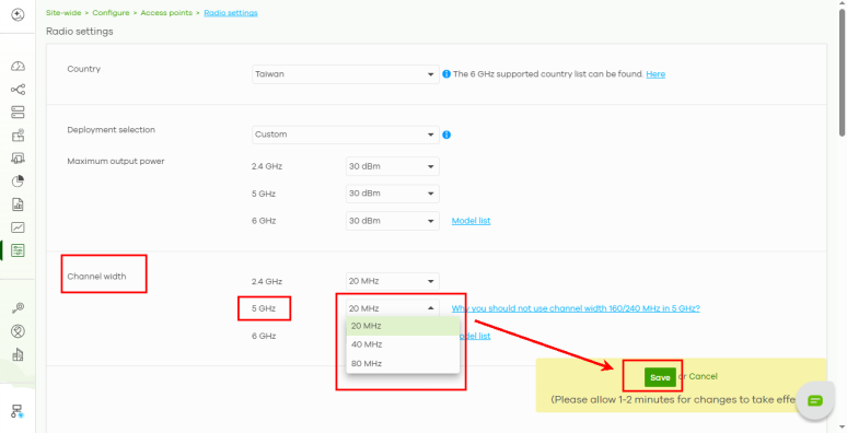
2 Go to Site-Wide >Configure > Access points > Radio settings. In Channel Width, select the channel width from the 5 GHz drop-down list. Click Save.
Monitor Channel Utilization
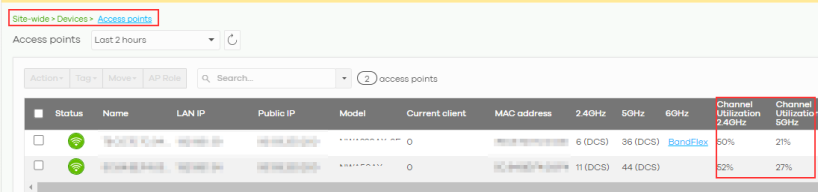
In the NCC portal, you can use Channel Utilization to check channel interference for each frequency band. To monitor channel utilization, go to Site-wide > Devices > Access points. Click the  icon. Then, select Channel Utilization 2.4 GHz, Channel Utilization 5 GHz, or Channel Utilization 6 GHz to view the channel utilization of each radio.
icon. Then, select Channel Utilization 2.4 GHz, Channel Utilization 5 GHz, or Channel Utilization 6 GHz to view the channel utilization of each radio.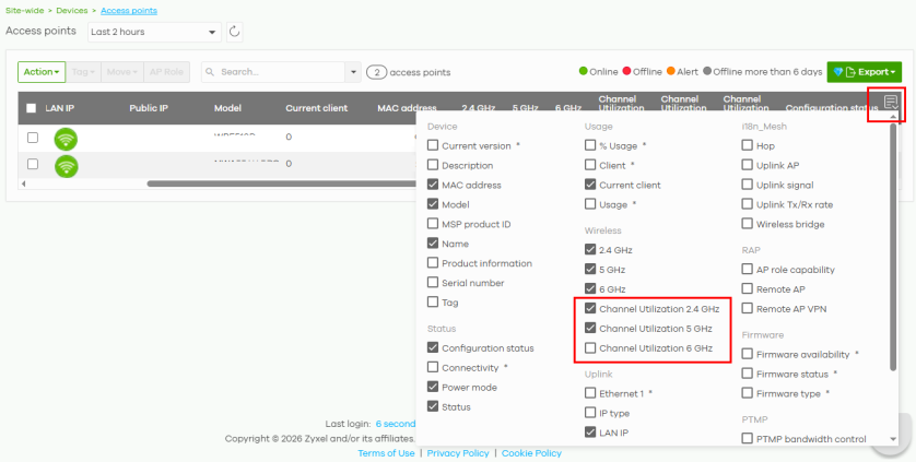
Check the Channel Utilization for each radio. High channel utilization may indicate one or more of the following:
• Nearby access points are using the same channel.
• Multiple WiFi networks are operating on the same channel.
• Non-WiFi devices, such as microwave ovens or Bluetooth devices, are causing interference.
• Access points are installed too close together.
Optimize Transmission Power
Do not set transmission power to max by default as it could cause interference with other Access Points. The transmission power should be set to minimize coverage overlap with neighboring Zyxel Devices while avoiding dead zones. The following table shows the recommended maximum transmission power for different deployment scenarios.
number of Zyxel Devices | RECOMMENDED maximum transmission power |
|---|---|
Single AP | 2.4 GHz: 30 dBm 5 GHz: 30 dBm 6 GHz: 30 dBm |
Low-density (2-5 APs) | 2.4 GHz: 20dBm 5 GHz: 30 dBm 6 GHz: 30 dBm |
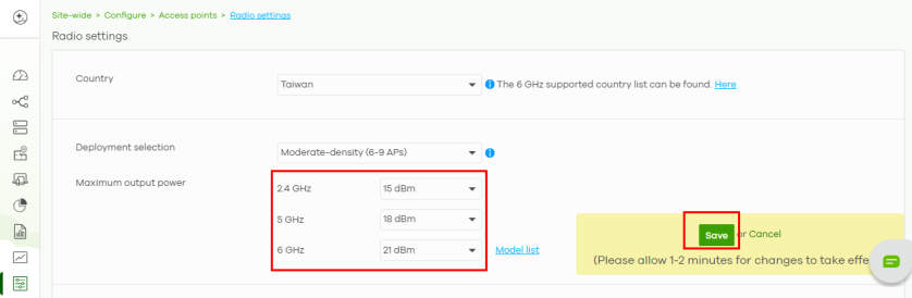
Moderate-density (6-9 APs) | 2.4 GHz: 15 dBm 5 GHz: 18 dBm 6 GHz: 21 dBm |
High-density (More than 10 APs) | 2.4 GHz: 12 dBm 5 GHz: 15 dBm 6 GHz: 18 dBm |
Based on the suggested maximum transmission power, reduce the transmit power by 3 to 5 dBm, and then fine-tune it in 2 dBm increments based on your WiFi environment.
For example, if the suggested maximum transmission power is 20 dBm, reduce it to 17 dBm or 15 dBm. If the signal becomes too weak, increase it from 17 dm to 19 dbm, or from 15 dbm to 17 dbm.
You can adjust the transmission power in one of the following management methods:
Standalone
1 Log in to the Web Configurator using the admin account and password on the device label.
2 To configure the transmit power, go to Configuration > Wireless > AP Management > WLAN Setting. For each radio, enter the suggested maximum transmission power from the Suggested Maximum Transmission Power table in Max Output Power (0 to 30 dBm). Adjust the value based on your WiFi environment. Click Apply.
Cloud Managed
1 Log in to the NCC portal.
2 Go to Site-Wide >Configure > Access points > Radio settings. Select your Zyxel Device’s deployment from the Deployment selection drop-down list.
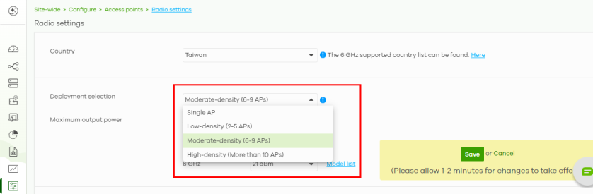
3 Adjust the value based on your WiFi environment. Click Save.
Optimize Roaming
You can do the following to optimize roaming quality:
Place the Zyxel Device for Strong WiFi Client Signals
Place the Zyxel Device based on the WiFi signal strength clients receive. You can check the signal strength of WiFi clients in one of the following management methods:
The following table shows the recommended signal strengths values:
signal strength | description |
|---|---|
greater than or equal to -65 dBm | This is the ideal signal strength throughout the coverage area for a good WiFi signal. For example, -60 dBm is greater than -65 dBm, |
less than or equal to -75 dBm | WiFi clients should begin roaming when the signal strength drops to or below this value. For example, -80 dBm is less than -75 dBm. |
Standalone
1 Log in to the Web Configurator using the admin account and password on the device label.
2 Go to Monitor > Wireless > Station Info > Station List, and click Refresh to display the latest values. In the example below, the WiFi client has a signal strength of -37 dBm, as shown in the Signal Strength field. Because -37 dBm is greater than -65 dBm, the WiFi client has a strong signal from the Zyxel Device.
Cloud Managed
1 Log in to the NCC portal.
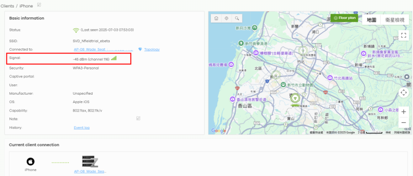
2 Go to Site-Wide > Clients > Client list, and select the WiFi client whose signal strength you want to check.
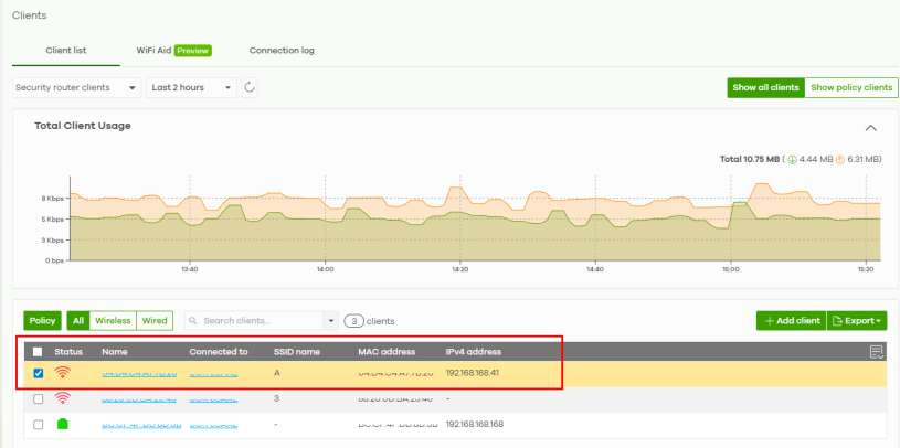
3 The WiFi clients’ details appear. In the example below, the signal strength of this iPhone is -45 dBm, as shown in the Signal field. Because -45 dBm is greater than -65 dBm, this iPhone has a strong signal from the Zyxel Device.
Configure the Disassociate Station Threshold
Disassociate station threshold allows the Zyxel Device to disconnect WiFi clients with weak signal strength so they can connect to another access point with a stronger signal. The recommended disassociate station threshold is shown below:
signal strength | description |
|---|---|
less than or equal to -88 dBm | If a WiFi client’s signal strength drops below -88 dBm, the Zyxel Device disconnects the WiFi client so it can reconnect to an AP with a stronger signal. For example, -100 dBm is less than -88 dBm. |
Configure disassociate station threshold in one of the below modes:
Standalone
1 Log in to the Web Configurator using the admin account and password on the device label.
2 Go to Configuration > Object > AP Profile > Radio. Select the radio profile you want to configure, and then click the Edit icon. The below example uses the Wiz_Radio_5G radio profile to configure disassociate station threshold.
3 The Edit Radio Profile appears. Select the Enable Signal Threshold checkbox, and enter a value in Disassociate Station Threshold between -20 to -105 dBm according to the Recommended Disassociate Station Threshold table. Select High, Standard, or Low from the Disassociate Aggressiveness drop-down list based on the how aggressively you want the Zyxel Device to disconnect WiFi clients with weak signal strength:
LEVEL | description |
|---|---|
High (Most aggressive) | The Zyxel Device disassociates inactive WiFi clients using the shortest inactivity detection interval. |
Standard (Moderate) | The Zyxel Device disassociates inactive WiFi clients using the default inactivity detection interval. |
Low (Least aggressive) | The Zyxel Device disassociates inactive WiFi clients using the longest inactivity detection interval. |
When finished, click OK.
To check the traffic status of your Zyxel Device:
• Standalone:
Go to Monitor > Network Status. The traffic statistics are displayed in the Port Statistics Table.
• Cloud Managed:
Go to Site-wide > Devices > Access points > Live tools. The traffic statistics, including the transmission rate over time, are displayed.
Cloud Managed
1 Log in to the NCC portal.
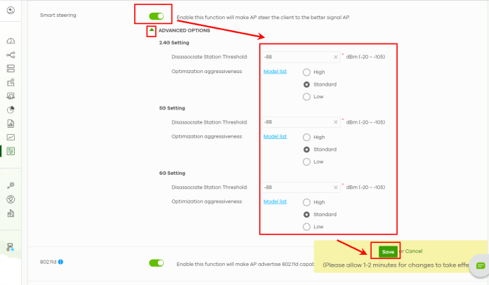
2 Go to Site-Wide > Configure > Access points > Radio settings, and enable Smart Steering. Click the arrow icon  to display the ADVANCED OPTIONS.
to display the ADVANCED OPTIONS.Enter a value between -20 to -105 dBm in Disassociate Station Threshold according to the Recommended Disassociate Station Threshold table. Select High, Standard, or Low from Optimization aggressiveness based on the how aggressively you want the Zyxel Device to disconnect WiFi clients with weak signal strength.
Limit Network Bandwidth for Each WiFi Client
Restricting network bandwidth for each WiFi client ensures that all clients have equitable access to the network, preventing a few WiFi clients from monopolizing the bandwidth.
1 Go to Configuration > Object > AP Profile > SSID > SSID List, select a profile and click Edit.
2 Enter the maximum transmission data rate (either in Mbps or Kbps) for each WiFi client in the Downlink field.
3 Click OK to save your changes.
Network Security
In this section, we show you how to:
Choose a Suitable Security Mode
Different Security Modes provide different levels of protection and authentication methods. They determine how users authenticate with the WiFi network and how WiFi traffic is encrypted.
This tutorial explains the differences between the following Security Modes and when to use each one.
• WEP
• WPA2
• WPA2-MIX
• WPA3
Using None as the Security Mode is not recommended because it provides no authentication or data encryption. Use this only for temporary testing or troubleshooting.Go to Configuration > Object > AP Profile > SSID > Security List to access the Security Profile screen.
The following table describes the authentication methods and encryption protocols used by each Security Mode.
Security mode | authentication | encryption |
|---|---|---|
None | None | None |
Enhanced-open | Opportunistic Wireless Encryption (OWE) | Advanced Encryption Standard (AES) |
WEP | Shared key | Rivest Cipher 4 (RC4) |
WPA | Personal (Pre-Shared Key) or Enterprise (RADIUS) | Temporal Key Integrity Protocol (TKIP) |
WPA2 | Personal (Pre-Shared Key) or Enterprise (RADIUS) | AES-CCMP CCMP stands for Counter Mode with Cipher Block Chaining Message Authentication Code Protocol. |
WPA2-MIX | Personal (Pre-Shared Key) or Enterprise (RADIUS) | TKIP (WPA) or AES-CCMP (WPA2) |
WPA3 | Personal (Pre-Shared Key) or Enterprise (RADIUS) | AES-GCMP / AES-CCMP GCMP stands for Galois/Counter Mode Protocol. |
Enhanced-open
Users connect to the WiFi network without entering a password while their WiFi traffic remains protected.
This Security Mode is suitable for:
• Public WiFi networks, such as airports, cafés and hotels.
WEP
This Security Mode is old and should not be used today. It’s an older WiFi security standard and can be easily compromised due to weakness in its encryption.
Use this only when supporting devices do not support newer security standards. WPA2
Uses AES-CCMP encryption to encrypt WiFi traffic. Users authenticate using either a shared password (Personal) or a RADIUS server (Enterprise).
This Security Mode is suitable for:
• Home WiFi network (WPA2-Personal).
• Office WiFi network (WPA2-Enterprise).
For example, in a small company, each employee has their own account. When an employee tries to connect to the office WiFi network, he needs to enter a Username and Password.
The Zyxel Device forwards the credentials to the RADIUS server. The RADIUS server verifies them, if they are valid, the connection is allowed.
WPA2-MIX
Allows both WPA and WPA2 clients to connect to the WiFi network. Use this mode if you have client devices that only support WPA and devices that support WPA2.
This Security Mode is suitable for:
• WPA devices, such as older printers and warehouse barcode scanners.
• WPA2 devices, such as laptops, smartphone, and tablets.
WPA3
Uses Simultaneous Authentication of Equals (SAE) for authentication and AES encryption to protect WiFi traffic. It provides stronger security than WPA2. It is the recommended Security Mode if your client devices support WPA3.
This Security Mode is suitable for:
• Organizations that require the highest level of WiFi security.
Change Security for a WiFi Network
Changing the security settings on a WiFi network enhances protection by blocking unauthorized client devices. This option is ideal for small WiFi networks with a few WiFi clients. For WiFi networks with a lot of clients, see RADIUS Server Setup for more information.
1 Go to the Configuration > Wireless > AP Management > WLAN Setting screen. Click Edit under the SSID profile to change the WiFi security.
2 The following screen appears, click the Edit icon next to Security Profile.
3 The following screen appears, select Personal and enter a pre-shared key from 8 to 63 case-sensitive keyboard characters in Pre-Shared Key. Click OK to save your changes.
RADIUS Server Setup
Setting up a RADIUS server on your Zyxel Device allows centralized user authentication and authorization, which enhances network security. This option is ideal for enterprise users who need to manage many WiFi clients.
1 Go to the Configuration > Object > AP Profile > SSID > Security List screen. Select a profile you want to configure for the RADIUS server and click Edit.
2 Set Authentication Settings to Enterprise to configure the RADIUS server. Enter the RADIUS server’s IP address, port number and secret. The Radius Server Secret must match the secret on the RADIUS server client. Click OK to save your changes.
Set Up Rogue AP Detection
This example shows you how to configure the rogue AP detection feature on the Zyxel Device. A rogue AP is a WiFi access point operating in a network’s coverage area that is not a sanctioned part of that network. See Rogue AP for background information on the rogue AP function and security considerations.
In this example, you want to ensure that your company’s data is not accessible to an attacker gaining entry to your WiFi network through a rogue AP.
Your WiFi network operates in an office building. It consists of four Zyxel access points (all NWAs) and a variable number of WiFi clients. You also know that the coffee shop on the ground floor has a WiFi network consisting of a single access point (AP 1), which can be detected and accessed from your floor of the building. There are no other static WiFi networks in your coverage area.
The following diagram shows the WiFi networks in your area. Your access points are marked A, B, C and D. You also have a computer, marked E, connected to the wired network. The coffee shop’s access point is marked 1.
WiFi Network Example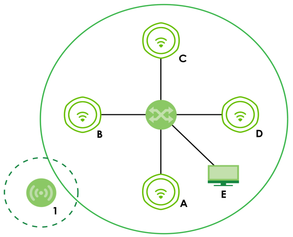
In the figure, the solid circle represents the range of your WiFi network, and the dashed circle represents the extent of the coffee shop’s WiFi network. Note that the two networks overlap. This means that one or more of your APs can detect the AP 1 in the other WiFi network.
When configuring the rogue AP feature on your Zyxel Device in this example, you will need to use the information in the following table. You need the IP addresses of your APs to access their Web configurators, and you need the MAC address of each AP to configure the friendly AP list.
DEVICE | IP ADDRESS | MAC ADDRESS |
|---|---|---|
Access Point A | 192.168.1.1 | 00:AA:00:AA:00:AA |
Access Point B | 192.168.1.2 | AA:00:AA:00:AA:00 |
Access Point C | 192.168.1.3 | A0:0A:A0:0A:A0:0A |
Access Point D | 192.168.1.4 | 0A:A0:0A:A0:0A:A0 |
Access Point 1 | Unknown | AF:AF:AF:FA:FA:FA |
You can detect the MAC addresses of other APs in the Monitor > Wireless > Detected Device screen. However, it is more secure to obtain the correct MAC addresses from another source and add them to the friendly AP list manually. For example, an attacker’s AP mimicking the correct SSID could be placed on the friendly AP list by accident, if selected from the list of auto-detected APs. In this example you have spoken to the coffee shop’s owner, who has told you the correct MAC address of his AP 1.
Set Up a Friendly AP List
To find rogue APs, create a list of known friendly APs, then scan for all APs in your coverage area. Check if other APs are known and if not add them to the Rogue AP list.
Take the following steps to set up and save a list of access points you want to allow in your network’s coverage area.
1 On a computer connected to the wired network (F in the previous figure), open your Internet browser and enter the URL of access point A (192.168.1.1). Login to the Web Configurator, go to Configuration > Rogue AP > Rogue/Friendly AP List and then click Add in the Rogue/Friendly AP list field.
2 Fill in the MAC and Description fields as in the following table. Click Add after you enter the details of each AP to include it in the list.
MAC ADDRESS | DESCRIPTION |
|---|---|
00:AA:00:AA:00:AA | My Access Point _A_ |
AA:00:AA:00:AA:00 | My Access Point _B_ |
A0:0A:A0:0A:A0:0A | My Access Point _C_ |
0A:A0:0A:A0:0A:A0 | My Access Point _D_ |
AF:AF:AF:FA:FA:FA | Coffee Shop Access Point _1_ |
You can add APs that are not part of your network to the friendly AP list, as long as you know that they do not pose a threat to your network’s security. 3 Next, click Apply to save the list of friendly APs in order to provide a backup and upload it to your other access points.
4 Click Exporting in the Friendly AP List Importing/Exporting field. If a window similar to the following appears, click Save.
5 Save the friendly AP list somewhere it can be accessed by all the other access points on the network. In this example, save it on the network file server. The default filename is “friendly”.
Import the Friendly AP List to Other APs
Access point A is now configured to do the following.
• Scan for access points in its coverage area
• Recognize friendly access points from a list
Now you need to configure the other WiFi access points in your network to do the same things.
For each access point, take the following steps.
1 From a computer on the wired network, enter the access point’s IP address and log into its Web Configurator.
2 Import the friendly AP list. Click Configuration > Wireless > Rogue AP > Rogue/Friendly AP List, and click Browse in the Friendly AP List Importing/Exporting field. Find the “friendly” file where you previously saved it on the network and click Open. Then, click Importing.
3 Check the Configuration > Wireless > Rogue AP > Rogue/Friendly AP List screen to ensure that the friendly AP list has been correctly uploaded.
Set Up a MAC Filter List
A MAC filter list blocks or allows a list of clients based on their MAC addresses, ensuring only authorized clients can access the network. This example shows how to block certain clients based on their MAC addresses.
1 Go to Configuration > Object > AP Profile > SSID > MAC Filter List and then click Add.
2 Fill in the Profile Name and select deny for Filter Action. Click Add to add a new MAC address to block. Enter the MAC addresses of the clients you want to block under the MAC field and then click OK.
Restrict Users’ Access to Specific Parts of Your Network
This example shows you how to allow certain users to access only specific parts of your network. You can do this by using multiple MAC filters and layer-2 isolation profiles.
Scenario
In this example, you run a company network in which certain employees must wirelessly access secure file servers containing valuable proprietary data.
You have two secure servers (1 and 2 in the following figure). WiFi user “Alice” (A) needs to access server 1 (but should not access server 2) and WiFi user “Bob” (B) needs to access server 2 (but should not access server 1). Your Zyxel Device is marked ZD. C is a workstation on your wired network, D is your main network switch, and E is the security gateway you use to connect to the Internet.
Getting Started: Example Network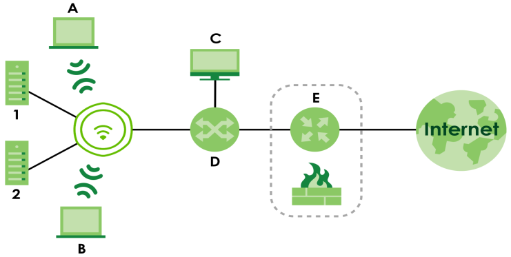
Your Requirements
1 You want to set up a WiFi network to allow only Alice to access server 1 and the Internet.
2 You want to set up a second WiFi network to allow only Bob to access server 1 and the Internet.
Setup
In this example, you have already set up the Zyxel Device in AP Mode (see WiFi Network Setup). It uses two SSID profiles simultaneously. You have configured each SSID profile as shown in the following table.
SSID Profile Name | SERVER_1 | SERVER_2 |
SSID | SSID_S1 | SSID_S2 |
Security | Security Profile security03: WPA2-PSK Hide SSID | Security Profile security04: WPA2-PSK Hide SSID |
Intra-BSS traffic blocking | Enabled | Enabled |
Each SSID profile already uses a different pre-shared key.
In this example, you will configure access limitations for each SSID profile. To do this, you will take the following steps.
1 Configure the SERVER_1 network’s SSID profile to use specific MAC filter and layer-2 isolation profiles.
2 Configure the SERVER_1 network’s MAC filter profile.
3 Configure the SERVER_1 network’s layer-2 isolation profile.
4 Repeat steps 1 to step 3 for the SERVER_2 network.
5 Check your settings and test the configuration.
To configure layer-2 isolation, you need to know the MAC addresses of the devices on your network, which are as follows.
DEVICE | LABEL | MAC ADDRESS |
|---|---|---|
Zyxel Device | ZD | BB:AA:99:88:77:66 |
Secure Server 1 | 1 | AA:99:88:77:66:55 |
Secure Server 2 | 2 | 99:88:77:66:55:44 |
Workstation | C | 88:77:66:55:44:33 |
Switch | D | 77:66:55:44:33:22 |
Security gateway | E | 66:55:44:33:22:11 |
To configure MAC filtering, you need to know the MAC addresses of the devices Alice and Bob use to connect to the network, which are as follows.
User | MAC Address |
|---|---|
Alice | 11:22:33:44:55:66 |
Bob | 22:33:44:55:66:77 |
Configure the SERVER_1 Network
First, you will set up the SERVER_1 network which allows Alice to access secure server 1 through the network switch.
You will configure the MAC filter to restrict access to Alice alone, and then configure layer-2 isolation to allow her to access only the network router, the file server and the Internet security gateway.
Take the following steps to configure the SERVER_1 network.
1 Go to Configuration > Object > AP Profile > SSID > SSID List. The following screen displays, showing the SSID profiles you already configured. Select SERVER_1’s entry and click Edit.
2 The following screen appears. Select l2Isolation03 for Layer-2 Isolation Profile, and select macfilter03 for MAC Filtering Profile. Click OK.
3 Click the Layer-2 Isolation List tab. Select the l2Isolation03’s entry and click Edit. The following screen displays.
4 Enter the network router’s MAC Address and add a Description (“NET_ROUTER” in this case) in Set 1’s entry.
5 Enter server 1’s MAC Address and add a Description (“SERVER_1” in this case) in Set 2’s entry.
6 Change the Profile Name to “L2-ISO_SERVER_1” and click OK. You have restricted users on the SERVER_1 network to access only the devices with the MAC addresses you entered.
7 Go to the MAC Filter List tab. Then, select macfilter03’s entry and click Edit.
8 Enter the MAC address of the device Alice uses to connect to the network in Set 1’s MAC Address field and enter her name in the Description field, as shown in the following figure. Change the Profile Name to “MacFilter_SERVER_1”. Select Allow from the Filter Action field and click OK.
You have restricted access to the SERVER_1 network to only the networking device whose MAC address you entered. The SERVER_1 network is now configured.
Configure the SERVER_2 Network
Next, you will configure the SERVER_2 network that allows Bob to access secure server 2 and the Internet.
To do this, repeat the procedure in Configure the SERVER_1 Network, substituting the following information.
SSID Screen | |
Index | 4 |
Profile Name | SERVER_2 |
SSID Edit (SERVER_2) Screen | |
L2 Isolation | l2Isolation04 |
MAC Filtering | macfilter04 |
Layer-2 Isolation (l2Isolation04) Screen | |
Profile Name | L2-ISO_SERVER-2 |
Set 1 | MAC Address: 77:66:55:44:33:22 Description: NET_ROUTER |
Set 2 | MAC Address: 99:88:77:66:55:44 Description: SERVER_2 |
Set 3 | MAC Address: 66:55:44:33:22:11 Description: GATEWAY |
MAC Filter (macfilter04) Edit Screen | |
Profile Name | MacFilter_SERVER_2 |
Set 1 | MAC Address: 22:33:44:55:66:77 Description: Bob |
Test Your WiFi Access Restrictions
Use the following sections to ensure that your WiFi networks are set up correctly.
Check Settings
Take the following steps to check that the Zyxel Device is using the correct SSIDs, MAC filters and layer-2 isolation profiles.
1 Click Configuration > Wireless > AP Management. Check that the correct SSID profiles are enabled, as shown in the following figure.
2 Next, go to Configuration > Object > AP Profile. Check that each configured SSID profile uses the correct Security, Layer-2 Isolation and MAC Filter profiles, as shown in the following figure.
Testing the Access Restrictions
Before you allow employees to use the network, you need to thoroughly test whether the setup behaves as it should. Take the following steps to do this.
1 Test the SERVER_1 network.
• Using Alice’s computer and WiFi client, and the correct security settings, do the following.
Attempt to access Server 1. You should be able to do so.
Attempt to access the Internet. You should be able to do so.
Attempt to access Server 2. You should be unable to do so. If you can do so, layer-2 isolation is misconfigured.
• Using Alice’s computer and WiFi client, and incorrect security settings, attempt to associate with the SERVER_1 network. You should be unable to do so. If you can do so, security is misconfigured.
• Using another computer and WiFi client, but with the correct security settings, attempt to associate with the SERVER_1 network. You should be unable to do so. If you can do so, MAC filtering is misconfigured.
2 Test the SERVER_2 network.
• Using Bob’s computer and WiFi client, and the correct security settings, do the following.
Attempt to access Server 2. You should be able to do so.
Attempt to access the Internet. You should be able to do so.
Attempt to access Server 1. You should be unable to do so. If you can do so, layer-2 isolation is misconfigured.
• Using Bob’s computer and WiFi client, and incorrect security settings, attempt to associate with the SERVER_2 network. You should be unable to do so. If you can do so, security is misconfigured.
• Using another computer and WiFi client, but with the correct security settings, attempt to associate with the SERVER_2 network. You should be unable to do so. If you can do so, MAC filtering is misconfigured.
If you cannot do something that you should be able to do, check the settings as described in Check Settings, and in the individual Security, layer-2 isolation and MAC filter profiles for the relevant network. If this does not help, see the Troubleshooting chapter in this User’s Guide.
Device Settings
In this section, we show you how to:
Change the Management IP Address
Change the management IP address of the Zyxel Device to ensure it does not duplicate the IP address of any other device on the network. If IP addresses are duplicated, you may be unable to access the Zyxel Device.
1 Set the computer’s IP address to be in the same subnet as the Zyxel Device. For example, the default static management IP address of the Zyxel Device is 192.168.1.2. Make sure your computer’s IP address is from 192.168.1.3~192.168.1.254.
2 Go to the Configuration > Network > IP Setting screen in the Web Configurator. Select the IP type to Static IP and specify a preferred IPv4 address in the IP Address field, for example, “192.168.1.10”. After clicking Apply, you will be disconnected from the Web Configurator due to the IP address change.
3 To check if the IP address of the Zyxel Device has been changed to “192.168.1.10”, enter the new IP address “192.168.1.10” in the address bar and see if you can log in to the Web Configurator successfully. Ensure that your computer’s IP address is in the same subnet as the Zyxel Device. For example, if the management IP address of the Zyxel Device is “192.168.1.10”, your computer’s IP address should be from 192.168.1.3~192.168.1.254.
Change the System Name
Changing the system name ensures that the Zyxel Device's name is not duplicated with other devices on the network, which may otherwise cause confusion for network administrators.
1 Go to the Configuration > System > Host Name screen and enter a new name with 1 to 64 alphanumeric characters in the System Name field. Spaces are not allowed. Click Apply to save your changes.
2 See the System Name field in the Dashboard screen to check if the new system name has been applied.
Change the Login Password
Change the Web Configuration login password to help secure your account.
1 Go to the Configuration > Object > User screen. Select an account and click the Edit icon.
2 The Edit User admin screen appears. Enter the new password with 4 to 63 characters. Spaces are not allowed. Reenter the new password and click OK.
Device Management Using Nebula
In this section, we will show you how to:
Create a Zyxel Account on the NCC Portal
1 Go to the NCC portal in one of two ways.
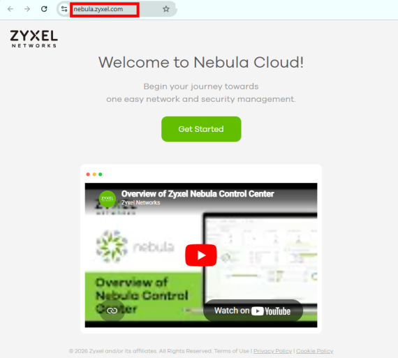
• Enter https://nebula.zyxel.com in a supported web browser. See the Nebula User’s Guide for more information about supported browsers.
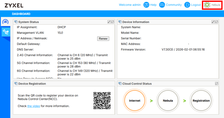
• Click the Nebula Control Center icon in the upper right of the Zyxel Device’s Web Configurator.
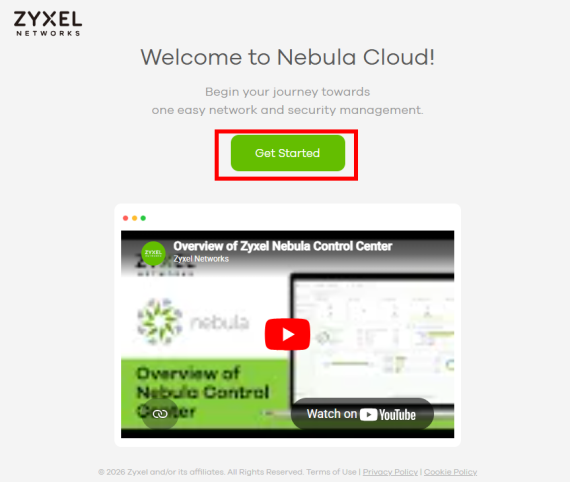
2 Click Get Started in the NCC portal.
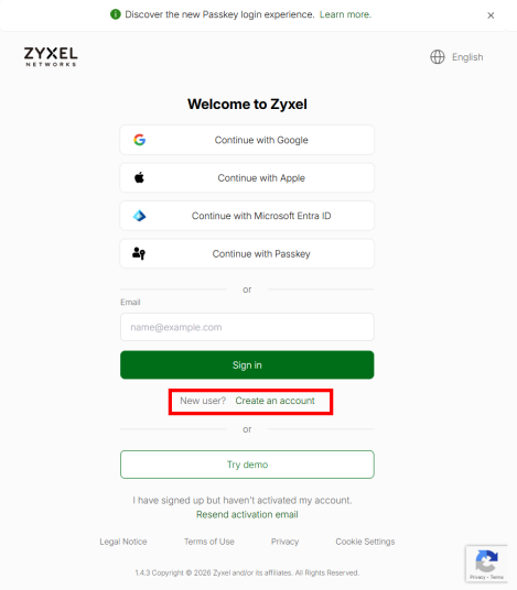
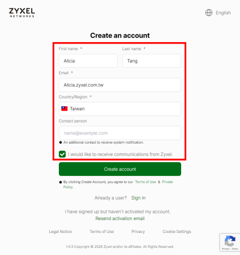
3 Click Create an account and you will be redirected to another screen where you can sign up for a Zyxel Account.
4 Enter your First name, Last name, Email, Country/Region, and Contact person. Select the checkbox to receive future information from Zyxel. Click Create Account.
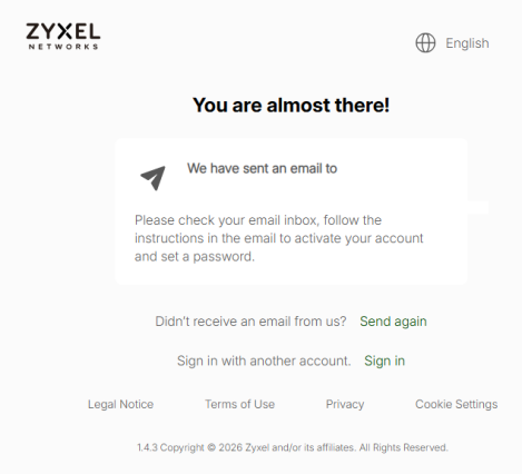
5 A notification informs you that a confirmation email will be sent to the registered email address on the NCC portal.
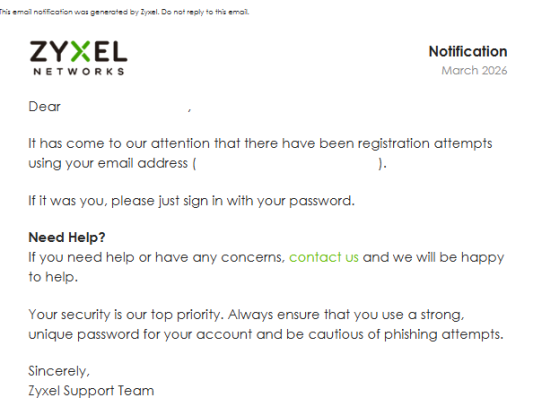
6 Check your email inbox. You will receive an email as shown below. Your new Zyxel Account has been created.
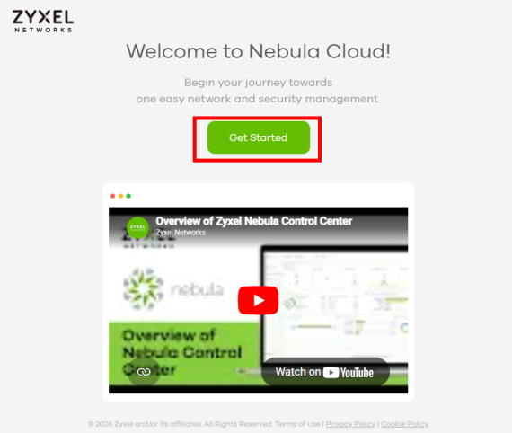
7 Go to the NCC portal and click Get Started.
8 Enter your email address, and click Sign in to log in to the NCC portal with your new Zyxel Account and password.
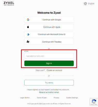
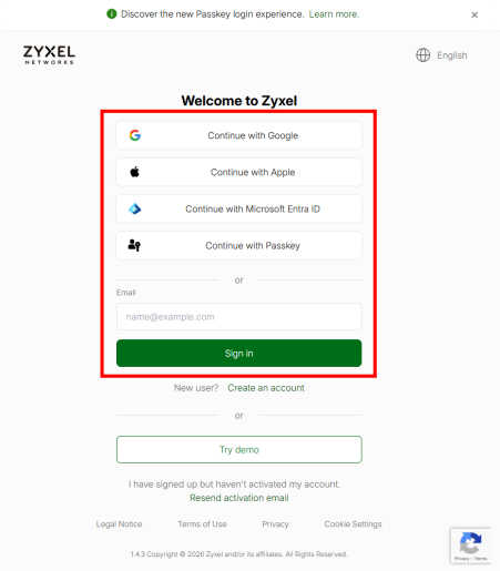
Register your Zyxel Device on the NCC Portal
Go to the NCC portal. Enter your existing Zyxel Account credentials, or log in using a social account such as Google, Apple, Microsoft Entra ID, or Passkey. Then, click Sign in.
If this is your first time logging in to the NCC portal, see First-Time Login to the NCC Portal.
First-Time Login to the NCC Portal
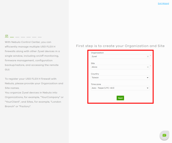
1 Follow the Nebula setup wizard to create an organization and site.
• The setup wizard helps you create an organization and site, add Nebula Devices, upgrade your Nebula Device firmware, and set up WiFi networks quickly.
• The wizard appears automatically after you log in the first time or if there is no organization created under your account.
• The wizard also starts when you click Create organization from the Organization drop-down list in the title bar.
2 Enter the Organization and Site names. Select your Country and Time zone. Click Next.
3 Enter the MAC address, Serial number, and Name of the Zyxel Device. Click the Add icon  , then click Next.
, then click Next.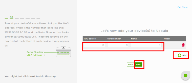
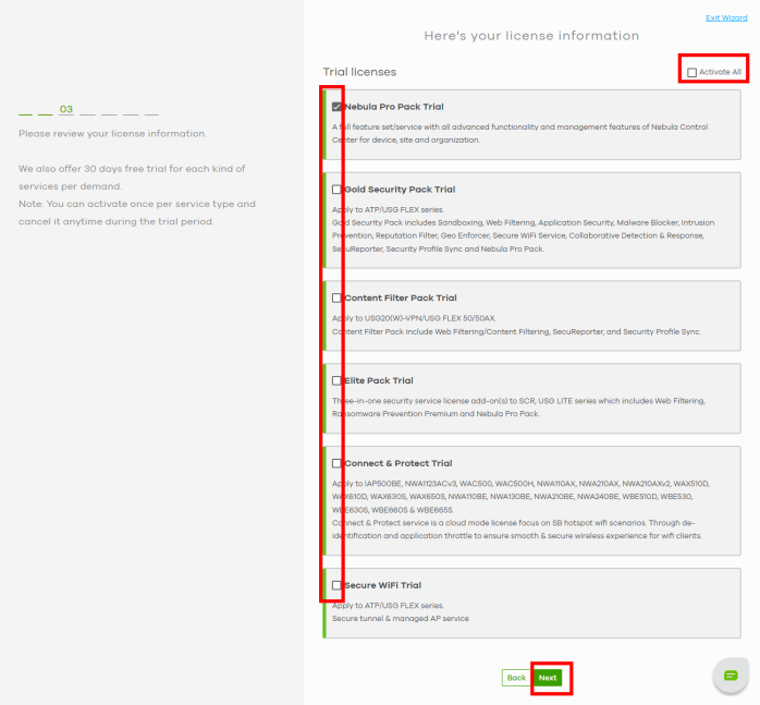
4 Select the trial license applicable to your Zyxel Device. You can also click Activate All to use all trial licenses. When finished, click Next.
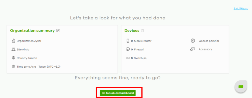
5 Check if the Organization summary and Devices information are correct. Once finished, click Go to Nebula Dashboard. Your Zyxel Devices are now registered on the NCC portal.
Regular Login to the NCC Portal
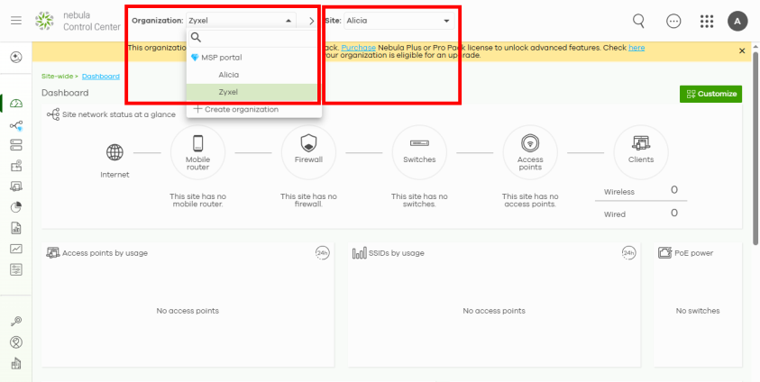
1 Select the Organization and Site where you want to register the Zyxel Device from the drop-down list at the top of the Dashboard screen.
2 Click the Devices icon on the left-hand bar of the Dashboard screen. Click the Add icon  to register a Zyxel Device.
to register a Zyxel Device.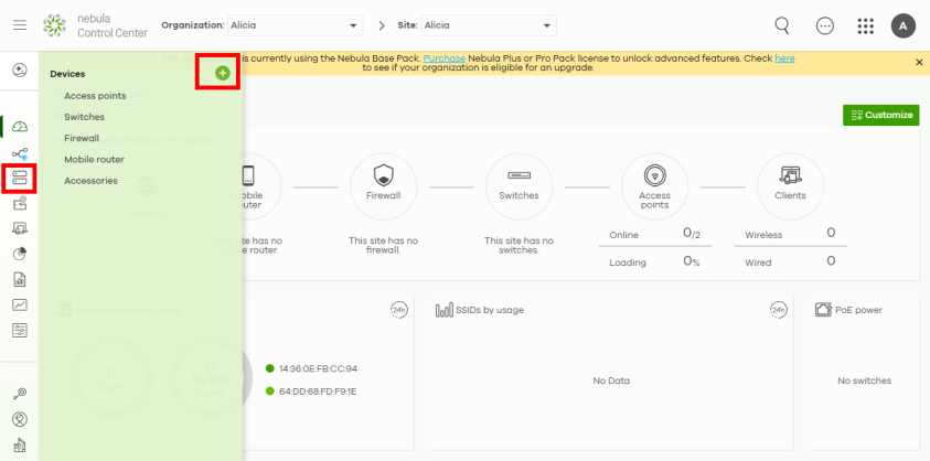
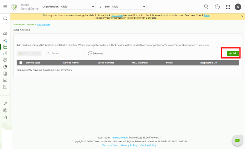
3 Click the +Add button on the right in the Add devices screen.
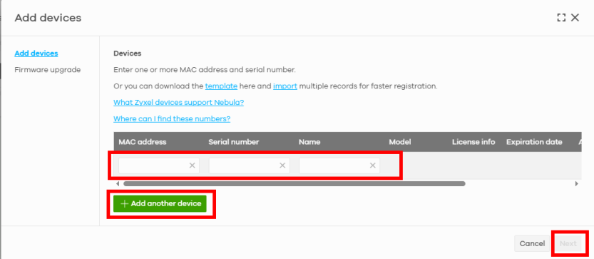
4 Enter the MAC address, Serial number, and Name of the Zyxel Device. The Serial number and Registration MAC address can be found on the Dashboard screen or on the device back label on the Zyxel Device. Click the Add another device button to add more devices if needed. When finished, click Next.
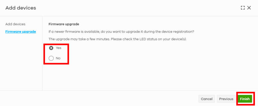
5 Select Yes to upgrade the Zyxel Device to the latest firmware. Click Finish to complete the registration of the Zyxel Device.
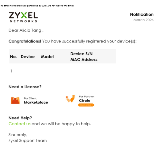
6 An email will be sent to inform you that the Zyxel Device has been successfully registered on the NCC portal.
Create a Zyxel Account with the Zyxel Nebula Mobile App
Download and open the Zyxel Nebula Mobile app in your mobile device (see Dashboard > Cloud Control Status to download the app.)
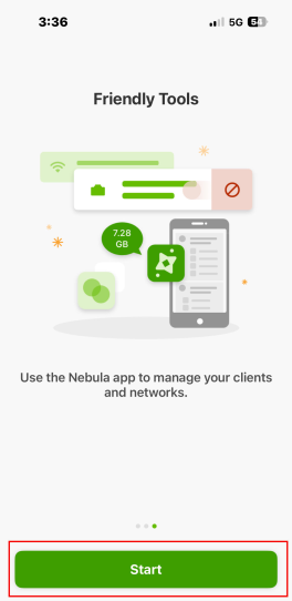
1 Tap Start.
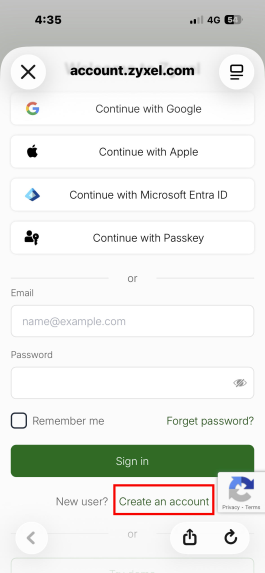
2 Tap Create an account. To return to the initial screen, tap the close icon in the upper-left corner.
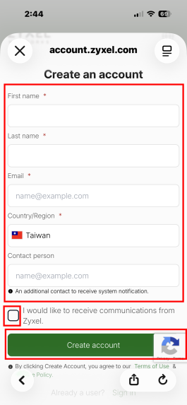
3 Enter your First name, Last name, Email, Country/Region, and Contact person. Select the checkbox to receive future information from Zyxel. Tap Create account.
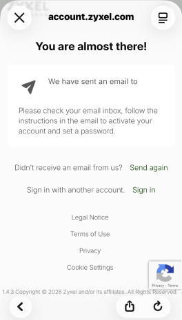
4 A notification informs you that a confirmation email will be sent to the registered email address on the NCC portal.
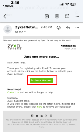
5 Check your email inbox. You will receive an email as shown below. Tap Activate Account. Your new Zyxel Account has been created.
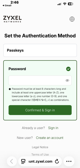
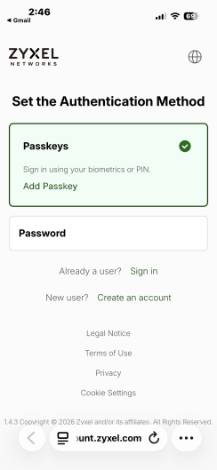
6 You will be prompted to choose an authentication method for your Zyxel Account in the Nebula Mobile app. Choose Passkeys to use fingerprint, Face ID, or PIN for authentication. Choose Password to set your own password for the Zyxel Account.
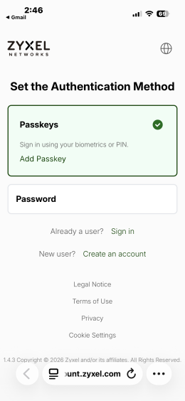
Passkeys
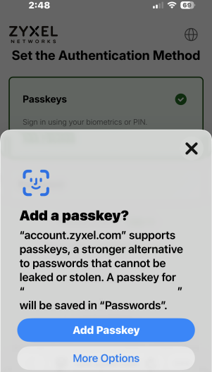
Tap Add Passkey. A notification prompts you to confirm adding the passkey. The example below uses Face ID as the passkey. For more details about passkeys, please refer to Zyxel Account Authentication.
Password
Enter the password and tap Confirmed & Sign in.
Use up to 8 single-byte characters for the Password, including at least one uppercase letter (A-Z), one lowercase letter (a-z), one number (0-9), and the following characters within the square brackets: [!@#$%^&*()_+] as combinations.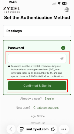
7 After setting the authentication method, the Nebula Mobile app prompts you to enable two-factor authentication. Tap Enable now to activate the feature, or tap Remind me later or Skip to close the screen.
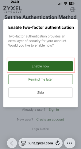
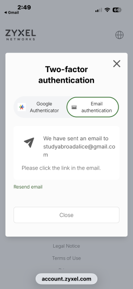
8 Choose either the Google Authenticator or Email authentication for the Two-factor authentication.
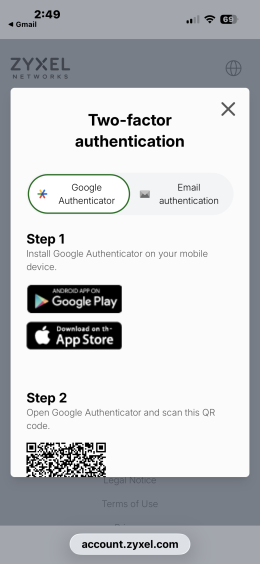
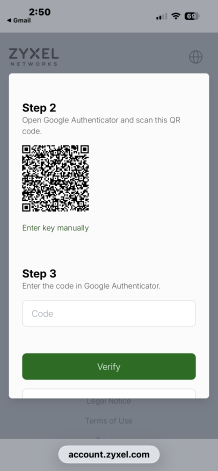
Google Authenticator
Follow the on-screen instructions to install the Google Authenticator. Scan the QR code with Google Authenticator and enter the code the Google Authenticator generates. Tap Verify to complete the authentication.
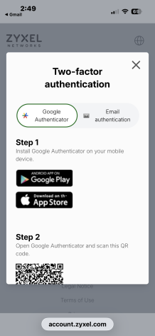
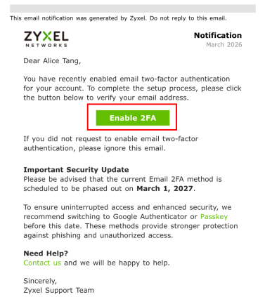
Email Authentication
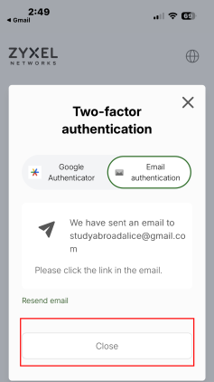
Check your email inbox. Tap Enable 2FA to activate the setting of Two-factor email authenticator. Tap Close to complete the process.
9 The Nebula Mobile app’s dashboard appears. You have successfully created a Zyxel Account.
Register your Zyxel Device with the Zyxel Nebula Mobile App
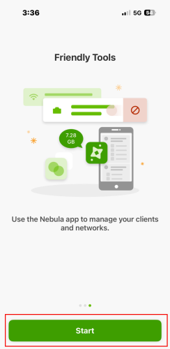
1 Open the Nebula Mobile app and tap Start.
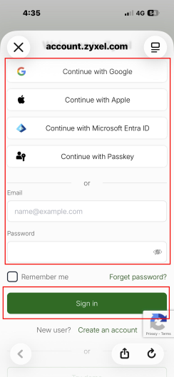
2 Log in to the Nebula Mobile app using any of the following methods:
• with a Google, Apple, or Microsoft Entra ID account
• with a passkey
• by entering your existing account information
Tap Sign in.
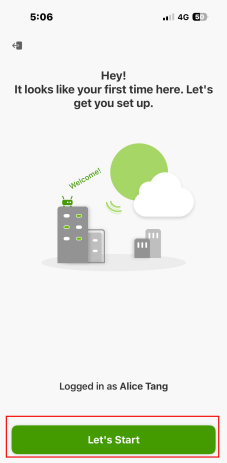
3 Tap Let’s Start to create your first site on the Nebula Mobile app.
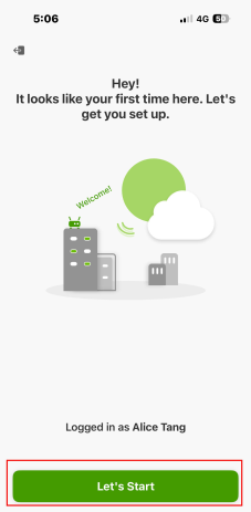
4 Enter your Site Name. An organization with the same name will be created automatically. Select your Country & Timezone from the drop-down list. The Timezone will adjust automatically based on the Country you select. Tap Create.
For the Site Name, enter a descriptive name for identification purposes. Use up to 64 single-byte characters, including the following characters within the square brackets: [0-9a-zA-Z_-`~!@#$%&*(_+-={}|[];'"./<> ?].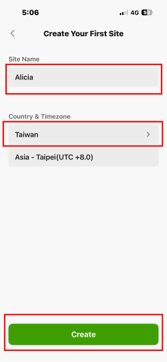
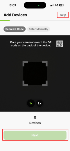
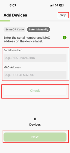
5 Add your Zyxel Device by scanning the QR code, or tap Enter Manually to enter the Serial Number and MAC Address from the Zyxel Device label. You can find the QR code:
• On a label on the Zyxel Device or
• On its box or
• In the Web Configurator at Dashboard > Cloud Control Status.
If you add a Zyxel Device manually, tap Check to confirm that the Serial Number and MAC Address are correct. After adding the Zyxel Device using either method, tap Next. If you do not want to add a Zyxel Device now, tap Skip.
6 Select a trial license pack and tap Next. Refer to License Finder if you are unsure which license pack to choose.

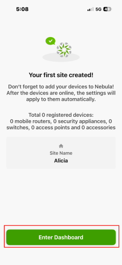
7 Tap Enter Dashboard.
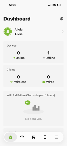
8 The Dashboard appears. The Zyxel Device has been successfully registered on the Nebula Mobile app.
Device Maintenance
In this section, we show you how to:
Upgrade the Firmware
Upload the firmware to the Zyxel Device for feature enhancements.
1 Download the correct firmware from the download library at the Zyxel website. The model code for the Zyxel Device in this example is ACIL. Unzip the file.
2 Go to Maintenance > File Manager > Firmware Package screen.
3 Click Browse... and select the file with a “.bin” extension to upload. Click Upload.
4 This process may take up to 2 minutes to finish. After 2 minutes, log on again and check your firmware version in the Dashboard screen.
Restore the Zyxel Device Configuration
The section shows you how to restore the configuration. You need to download and upload the configuration file to restore the configuration on the Zyxel Device.
Filename | description |
|---|---|
autobackup-x.xx.conf | This is the configuration file that the Zyxel Device automatically backs up when upgrading the firmware. |
startup-config.conf | This is the configuration file that the Zyxel Device is currently using. |
system-default.conf | This is the Zyxel Device’s default settings. |
lastgood.conf | This is the most recently used (valid) configuration file that was saved when the Zyxel Device last restarted. |
Download the Zyxel Device Configuration
You should regularly download your configuration especially before you make major configuration changes.
1 Go to the Maintenance > File Manager > Configuration File screen.
2 Under the Configuration Files, select startup-config.conf and click Download. The current configuration file that the Zyxel Device is using is saved to your computer. You can rename the configuration file to include the date you downloaded it. For example, startup-config.conf_20240716.
Upload the Zyxel Device Configuration
This section shows how to upload a previously saved configuration file from your computer to the Zyxel Device. You might need to do this to recover settings after a reset or to fix problems after configuration changes.
1 Go to the Maintenance > File Manager > Configuration File screen. Under Upload Configuration File, click Browse... and then select the configuration file that you saved. Click Upload.
2 You are logged out of the Web Configurator after the configuration file is successfully uploaded. Wait for one minute before logging into the Zyxel Device again.
Log and Report
In this section, we show you how to:
Daily Email Report Setup
In this example, you will configure the first of your Zyxel Device to send a log message to your email inbox.
Some models do not support the email daily report feature.1 Go to Configuration > Log & Report > Log Setting. Select the item and click Edit.The following screen appears. In this example, your mail server’s IP address is 192.168.1.25. Enter this IP address in the Mail Server field.
2 Enter a subject line for the alert emails in the Mail Subject field. Choose a subject that is eye-catching and identifies the access point - in this example, “ALERT_Access_Point_A”.
3 Enter the email address to which you want alerts to be sent (myname1@myfirm.com, in this example). Click Apply.
Back Up Logs to a Remote Server
Backing up logs to a remote server allows you to store large amounts of log data and prevent log data lost on your Zyxel Device. The Zyxel Device can keep at most 512 logs. If the logs exceed this number, the oldest logs will be lost.
1 Go to Configuration > Log & Report > Log Setting. Select a remote server to configure, and then click Edit.
2 The following screen appears. Select Active and enter the IPv4 address or name of the remote server in the Server Address field to send the logs. Then, select a log facility. The log facility allows you to log the messages to different files in the syslog server. Please see the documentation for your syslog program for more information.
3 Select the type of logs you want to back up on the remote server. The following are the log settings represented by the icons.
• Red X - Do not send the remote server logs for any log category.
• Green checkmark - Send the remote server log messages and alerts for all log categories.
• Yellow checkmark - Send the remote server log messages, alerts, and debugging information for all log categories.
4 Click OK to save your changes.
Collect Diagnostic Information
Diagnostic information helps you or customer support troubleshoot issues on the Zyxel Device. You can collect diagnostic information in both standalone and cloud-managed modes.
Collect Diagnostic Information in Standalone Mode
1 Log in to the Web Configurator using 192.168.1.2 or the DHCP-assigned IP address of the Zyxel Device.
If you do not know the Zyxel Device’s IP address, use ZON to discover nearby Zyxel Devices. In the example below, click the Web GUI icon or enter 192.168.1.58 in the browser address bar.2 Go to Maintenance > Diagnostics > Diagnostics and click Collect Now at the bottom of the screen.
3 The Debug Information Collector screen appears. Wait until the collection process to complete.
4 When the collection is complete, click Download to save the diagnostic information.
5 When the collection is complete, click Download to save the diagnostic information.
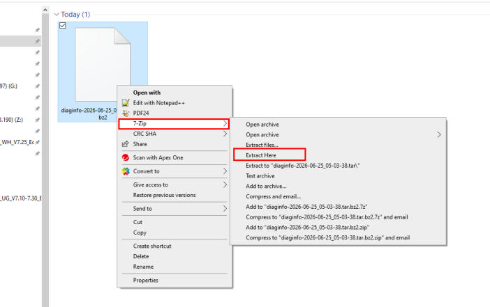
6 In the example below, the diagnostic file is downloaded to the computer’s Downloads folder. The file name, ‘diaginfo-2026-06-25_05-03-38.tar.bz2’, indicates that the file was downloaded at 05:03:38 on June 25, 2026. Right-click the file and select 7-Zip > Extract Here, or use another file extraction tool to extract the file.
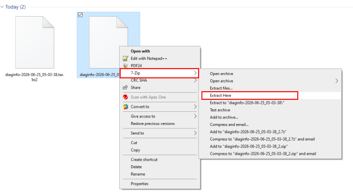
7 The extracted file, diaginfo-2026-06-25_05-03-38.tar, appears. Repeat the previous step to extract this file.
8 The debug folder appears.
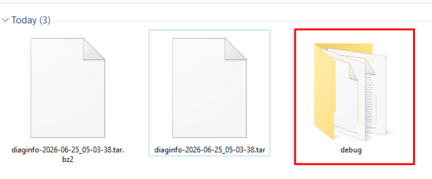
Click the debug folder to view the diagnostic files.
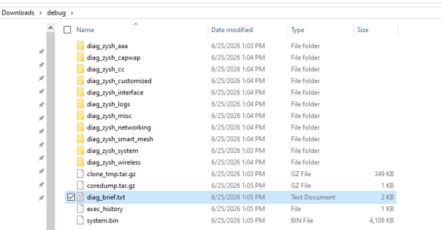
These folders contain the raw diagnostic data for troubleshooting. The folders in the debug folder are organized by the main features of the Zyxel Device and include the following:
• diag_zysh_aaa: Authentication and authorization information, including IEEE 802.1X, RADIUS, and authentication logs.
• diag_zysh_capwap: CAPWAP information for AP management by a wireless controller.
• diag_zysh_cc: Nebula Control Center (NCC) connection and cloud management information.
• diag_zysh_customized:Diagnostic information collected using a user-defined script that specifies additional diagnostic commands.
• diag_zysh_interface: Network interface configuration and status, including IP addresses and interface statistics.
• diag_zysh_logs: System and application log files.
• diag_zysh_misc: Miscellaneous diagnostic information.
• diag_zysh_networking: Network configuration and status, including routing, DNS, DHCP, and connectivity information.
• diag_zysh_smart_mesh: Smart Mesh (WDS) configuration and mesh connection status.
• diag_zysh_system: System information, including firmware, CPU, memory, storage, and running processes.
• diag_zysh_wireless: Wireless configuration and status, including radio settings, channels, SSIDs, clients, and signal information.
Click diag_brief.txt to view a summary of the diagnostic information. This text file provides an overview of the Zyxel Device's system status, including CPU and memory usage, running processes, cloud connection status, and a summary of detected errors for quick troubleshooting.
Mem: 474592K used, 408608K free, 21760K shrd, 11928K buff, 94196K cached CPU: 0.0% usr 2.3% sys 0.0% nic 95.3% idle 0.0% io 0.0% irq 2.3% sirq Load average: 2.85 2.36 2.20 3/275 11493 PID PPID USER STAT VSZ %VSZ CPU %CPU COMMAND 17288 17278 root S< 56612 6.3 3 0.0 /usr/bin/netopeer-server 7391 7383 root S 20232 2.2 3 0.0 /bin/zyshd 20498 1 root S 19264 2.1 0 0.0 /usr/sbin/radiusd -t -d /var/zyxel/raddb/ 4819 1 root S 14752 1.6 3 0.0 hostapd -g /var/run/hostapd/global -B -P /var/run/hostapd-global.pid -f /tmp/hostapd-global.log 4829 1 root S 14028 1.5 3 0.0 wpa_supplicant -g /var/run/wpa_supplicant/global -B -P /var/run/wpa_supplicant-global.pid -f /tmp/ws-global.log 9127 1 root S 12000 1.3 1 0.0 /usr/sbin/smart_mesh \n MEM REPORT: _____________________________________________ MEM LEAK CHECK: _____________________________________________ [OK] No memory leak dump files found. NEBULA REPORT: NEBULA CLOUD STATUS: _____________________________________________ [OK] successfully connected to the Nebula. NEBULA INTERNET STATUS: _____________________________________________ [OK] This access point is connected to the Internet. AAA REPORT: radius server IP/port [CAPWAP] CAPWAP Ping Test: Ping total: N/A Ping Time stamps: N/A CAPWAP Lost Echo Ping Test: Ping total: N/A Ping Time stamps: N/A CAPWAP Not RUN state: Total: N/A Windows: N/A [Smart Mesh Check] smart_mesh_dbg_log (ERROR lines): [Wed Jun 24 02:26:59 2026] is_nap_registed:825 : (ERROR) No child process [Wed Jun 24 02:26:59 2026] check_site_id_file:1227 : (ERROR) /etc/zyxel/ftp/smart_mesh/site_id file doesn't exist. [Wed Jun 24 02:26:59 2026] is_nap_registed:825 : (ERROR) No such file or directory [Wed Jun 24 02:27:11 2026] is_nap_registed:825 : (ERROR) No such file or directory [Wed Jun 24 02:27:11 2026] is_nap_registed:825 : (ERROR) No such file or directory |
Collect Diagnostic Information in Cloud-Managed Mode
To learn how to create a Zyxel Account and register a Zyxel Device using the Nebula Control Center (NCC) web portal or the Zyxel Nebula Mobile App, see Device Management Using Nebula for step-by-step instructions.
1 On your computer, enter https://nebula.zyxel.com in a supported web browser. The NCC web portal Dashboard displays. Click the Devices icon in the left-hand bar, and then click Access points.
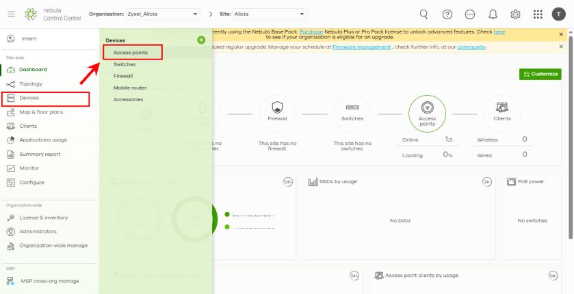
2 In the Zyxel Device list, find the Zyxel Device for which you want to collect diagnostic information. In the example below, the LAN IP address is 192.168.1.34.
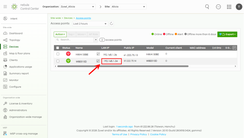
3 Connect a device, such as a computer or notebook, to the same subnet as the Zyxel Device. In this example, a notebook is used to access the Zyxel Device’s Web Configurator. In the screen above, the Zyxel Device’s IP address is 192.168.1.34, so the notebook must use an IP address in the range 192.168.1.1 to 192.168.1.254.
4 On the notebook, open a web browser and enter 192.168.1.34. The Zyxel Device login screen appears. Enter your user name and password.
For the password, return to the NCC web portal on your computer. In the Dashboard, click the Configure icon in the left-hand bar, and then click Site Settings.
In Device configuration > Local credentials, find the Password. Use this Password to log in to your Zyxel Device. In the example below, the password is ‘eX86J%Hxn93B’.
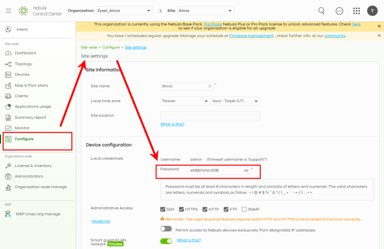
5 In the Zyxel Device Cloud-Managed Web Configurator, go to Maintenance > Diagnostics > Diagnostics. Click Collect Now.
6 The Debug Information Collector screen appears. Wait until the collection process to complete.
7 When the collection is complete, click Download to save the diagnostic information.
8 In the example below, the diagnostic file is downloaded to the computer’s Downloads folder. The file name, ‘diaginfo-2026-06-25_05-03-38.tar.bz2’, indicates that the file was downloaded at 05:03:38 on June 25, 2026. Right-click the file and select 7-Zip > Extract Here, or use another file extraction tool to extract the file.
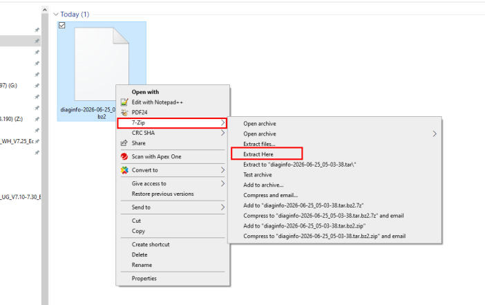
9 The extracted file, diaginfo-2026-06-25_05-03-38.tar, appears. Repeat the previous step to extract this file.
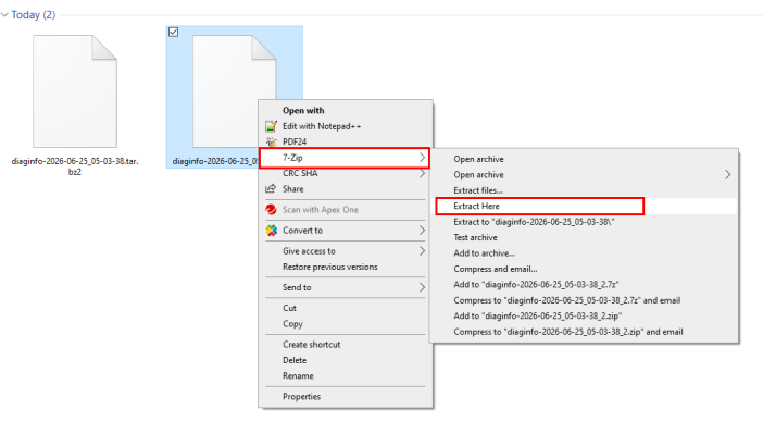
10 The debug folder appears.
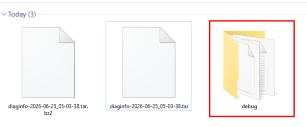
Click the debug folder to view the diagnostic files.
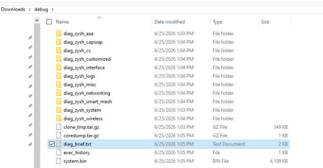
These folders contain the raw diagnostic data for troubleshooting. The folders in the debug folder are organized by the main features of the Zyxel Device and include the following:
• diag_zysh_aaa: Authentication and authorization information, including IEEE 802.1X, RADIUS, and authentication logs.
• diag_zysh_capwap: CAPWAP information for AP management by a wireless controller.
• diag_zysh_cc: Nebula Control Center (NCC) connection and cloud management information.
• diag_zysh_customized:Diagnostic information collected using a user-defined script that specifies additional diagnostic commands.
• diag_zysh_interface: Network interface configuration and status, including IP addresses and interface statistics.
• diag_zysh_logs: System and application log files.
• diag_zysh_misc: Miscellaneous diagnostic information.
• diag_zysh_networking: Network configuration and status, including routing, DNS, DHCP, and connectivity information.
• diag_zysh_smart_mesh: Smart Mesh (WDS) configuration and mesh connection status.
• diag_zysh_system: System information, including firmware, CPU, memory, storage, and running processes.
• diag_zysh_wireless: Wireless configuration and status, including radio settings, channels, SSIDs, clients, and signal information.
Click diag_brief.txt to view a summary of the diagnostic information. This text file provides an overview of the Zyxel Device's system status, including CPU and memory usage, running processes, cloud connection status, and a summary of detected errors for quick troubleshooting.
Mem: 474592K used, 408608K free, 21760K shrd, 11928K buff, 94196K cached CPU: 0.0% usr 2.3% sys 0.0% nic 95.3% idle 0.0% io 0.0% irq 2.3% sirq Load average: 2.85 2.36 2.20 3/275 11493 PID PPID USER STAT VSZ %VSZ CPU %CPU COMMAND 17288 17278 root S< 56612 6.3 3 0.0 /usr/bin/netopeer-server 7391 7383 root S 20232 2.2 3 0.0 /bin/zyshd 20498 1 root S 19264 2.1 0 0.0 /usr/sbin/radiusd -t -d /var/zyxel/raddb/ 4819 1 root S 14752 1.6 3 0.0 hostapd -g /var/run/hostapd/global -B -P /var/run/hostapd-global.pid -f /tmp/hostapd-global.log 4829 1 root S 14028 1.5 3 0.0 wpa_supplicant -g /var/run/wpa_supplicant/global -B -P /var/run/wpa_supplicant-global.pid -f /tmp/ws-global.log 9127 1 root S 12000 1.3 1 0.0 /usr/sbin/smart_mesh \n MEM REPORT: _____________________________________________ MEM LEAK CHECK: _____________________________________________ [OK] No memory leak dump files found. NEBULA REPORT: NEBULA CLOUD STATUS: _____________________________________________ [OK] successfully connected to the Nebula. NEBULA INTERNET STATUS: _____________________________________________ [OK] This access point is connected to the Internet. AAA REPORT: radius server IP/port [CAPWAP] CAPWAP Ping Test: Ping total: N/A Ping Time stamps: N/A CAPWAP Lost Echo Ping Test: Ping total: N/A Ping Time stamps: N/A CAPWAP Not RUN state: Total: N/A Windows: N/A [Smart Mesh Check] smart_mesh_dbg_log (ERROR lines): [Wed Jun 24 02:26:59 2026] is_nap_registed:825 : (ERROR) No child process [Wed Jun 24 02:26:59 2026] check_site_id_file:1227 : (ERROR) /etc/zyxel/ftp/smart_mesh/site_id file doesn't exist. [Wed Jun 24 02:26:59 2026] is_nap_registed:825 : (ERROR) No such file or directory [Wed Jun 24 02:27:11 2026] is_nap_registed:825 : (ERROR) No such file or directory [Wed Jun 24 02:27:11 2026] is_nap_registed:825 : (ERROR) No such file or directory |
Collect Diagnostic Information from the Nebula Control Center
To learn how to create a Zyxel Account and register a Zyxel Device using the Nebula Control Center (NCC) web portal or the Zyxel Nebula Mobile App, see Device Management Using Nebula for step-by-step instructions.
1 On your computer, enter https://nebula.zyxel.com in a supported web browser. The NCC web portal Dashboard appears. Click the Monitor icon in the left-hand bar, and then go to Access points > Event log.
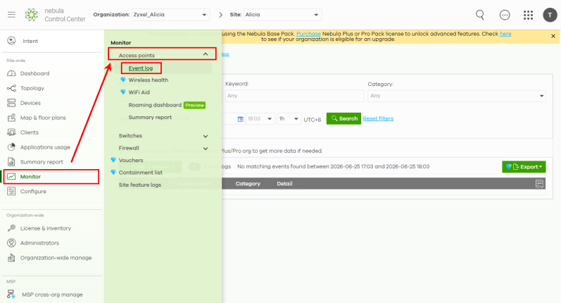
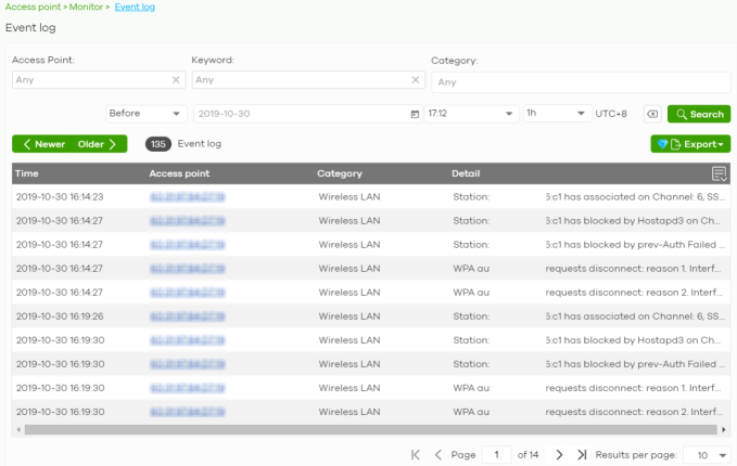
2 Use this screen to view Zyxel Device log messages. You can filter the displayed log messages by Zyxel Device name, keyword, event type, date and time, or time range. For more information, refer to the NCC User’s Guide.
Remote Access to the Zyxel Device
This section shows you how to configure WAN access for a specific trusted computer through HTTPS, HTTP or SSH to the Zyxel Device. Remote management determines which interface and web services are allowed to access the Zyxel Device.
Perform the following to find the options to configure remote access to your Zyxel Device.
HTTPS / HTTP
1 Go to the Configuration > System > Service Control screen. Select whether you want to access the Zyxel Device remotely through HTTPS or HTTP. Click Apply to save your changes.
The HTTPS server listens on port 443 by default. If you change the HTTPS server port to a different number on the Zyxel Device, for example 8443, then you must notify people who need to access the Zyxel Device Web Configurator to use “https://Zyxel Device IP Address:8443” as the URL.SSH
Go to the Configuration > System > SSH screen. Select whether you want to access the Zyxel Device remotely through SSH. Click Apply to save your changes. You may change the server port number for a service if needed, however you must use the same port number in order to use that service for remote management.