Cellular WAN Status
Cellular WAN Status Overview
View the cellular connection details and signal strength value that you can use as reference for positioning the Zyxel Device, as well as SIM card and module information.
Cellular WAN Status
To open this screen, click System Monitor > Cellular WAN Status. Cellular information is available on this screen only when you insert a valid SIM card in the Zyxel Device.
System Monitor > Cellular WAN Status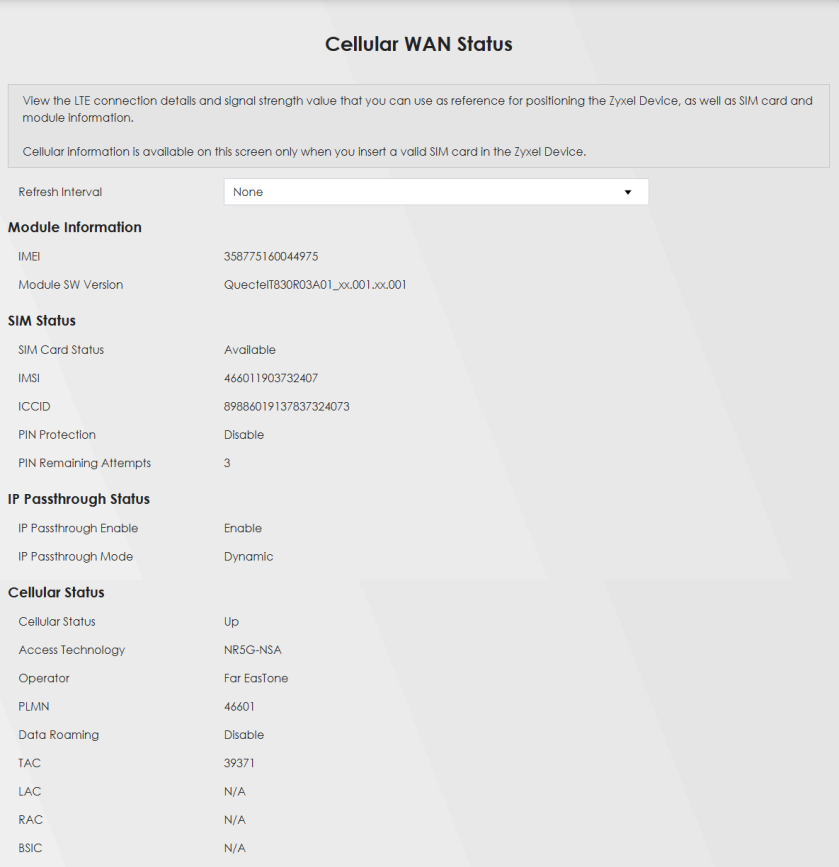
System Monitor > Cellular WAN Status (continued)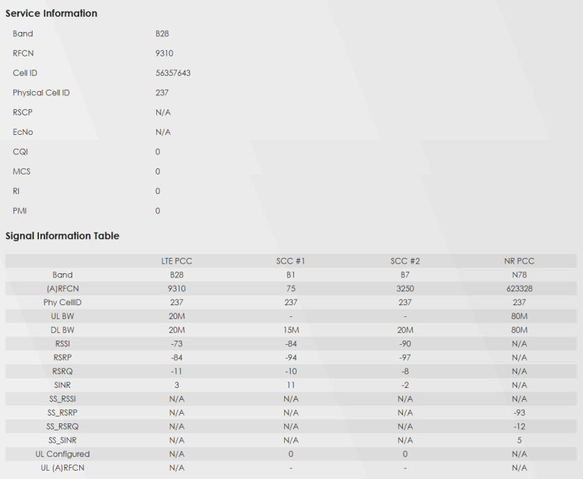
The following table describes the labels in this screen.
Label | Description |
|---|---|
Refresh Interval | Select the time interval the Zyxel Device will check and refresh the fields shown on this screen. Select None to stop detection. |
Module Information | |
IMEI | This shows the International Mobile Equipment Identity of the Zyxel Device. |
Module SW Version | This shows the software version of the cellular module. |
SIM Status | |
SIM Card Status | This displays the SIM card status: None – the Zyxel Device does not detect that there is a SIM card inserted. Waiting SIM Available – the SIM card is detected but not available yet. Available – the SIM card Locked – the SIM card has PIN code security, but you did not enter the PIN code yet. Blocked – you entered an incorrect PIN code too many times, so the SIM card has been locked; call the ISP for a PUK (Pin Unlock Key) to unlock the SIM card. Error - the Zyxel Device detected that the SIM card has errors. |
IMSI | This displays the International Mobile Subscriber Identity (IMSI) of the installed SIM card. An IMSI is a unique ID used to identify a mobile subscriber in a mobile network. |
ICCID | Integrated Circuit Card Identifier (ICCID). This is the serial number of the SIM card. |
PIN Protection | A PIN (Personal Identification Number) code is a key to a SIM card. Without the PIN code, you cannot use the SIM card. Shows Enable if the service provider requires you to enter a PIN to use the SIM card and PIN Protection is enabled. Shows Disable if the service provider lets you use the SIM without inputting a PIN. |
PIN Remaining Attempts | This is how many more times you can try to enter the PIN code before the ISP blocks your SIM card. |
IP Passthrough Status | |
IP Passthrough Enable | This displays if IP Passthrough is enabled on the Zyxel Device. IP Passthrough allows a LAN computer on the local network of the Zyxel Device to have access to web services using the public IP address. When IP Passthrough is configured, all traffic is forwarded to the first LAN computer on the local network and will not go through NAT. |
IP Passthrough Mode | This displays the IP Passthrough mode. This displays Dynamic and the Zyxel Device will allow traffic to be forwarded to the first LAN computer requesting an IP address from the Zyxel Device. This displays Fixed and the Zyxel Device will allow traffic to be forwarded to a specific LAN computer on the local network of the Zyxel Device. |
Cellular Status | |
Cellular Status | This displays the status of the cellular Internet connection. |
Data Roaming | This displays if data roaming is enabled on the Zyxel Device. Data roaming is to use your Zyxel Device in an area which is not covered by your service provider. Enable roaming to ensure that your Zyxel Device is kept connected to the Internet when you are traveling outside the geographical coverage area of the network to which you are registered. |
Operator | This displays the name of the service provider. |
PLMN | This displays the PLMN number. |
Antenna Status | This displays Internal when the INT EXT switch is set to INT. Use the Zyxel Device’s internal antenna to get cellular signal. This displays External when the INT EXT switch is set to EXT. Connect external antennas to the Zyxel Device’s to strengthen the cellular signal. See Panel Ports for more information. |
Service Information | |
Access Technology | This displays the type of the mobile network to which the Zyxel Device is connecting. |
Band | This displays the current cellular band of your Zyxel Device. |
RSSI (dBm) | This displays the strength of the Wi-Fi signal between an associated wireless station and an AP. The normal range is –30 dBm to –79 dBm. If the value drops below –80 dBm, try moving the associated wireless station closer to the Zyxel Device to get better signal strength. |
Cell ID | This shows the cell ID, which is a unique number used to identify the Base Transceiver Station to which the Zyxel Device is connecting. The value depends on the Current Access Technology: • For GPRS, it is the Cell Identity as specified in 3GPP-TS.25.331. • For UMTS, it is the Cell Identity as defined in SIB3 3GPP-TS.25.331, 3GPP-TS.24.008. • For LTE, it is the 28-bit binary number Cell Identity as specified in SIB1 in 3GPP-TS.36.331. The value is ‘0’ (zero) or ‘N/A’ if there is no network connection. |
Physical Cell ID | This shows the Physical Cell ID (PCI), which are queries and replies between the Zyxel Device and the mobile network it is connecting to. The normal range is 1 to 504. |
UL Bandwidth (MHz) | This shows the cellular channel bandwidth from the Zyxel Device to the base station. According to 3GPP specifications, the bandwidths defined by the standard are 1.4, 3, 5, 10, 15, and 20 MHz. The wider the bandwidth the higher the throughput. |
DL Bandwidth (MHz) | This shows the cellular channel bandwidth from the base station to the Zyxel Device. According to 3GPP specifications, the bandwidths defined by the standard are 1.4, 3, 5, 10, 15, and 20 MHz. The wider the bandwidth the higher the throughput. |
RFCN | This displays the Radio Frequency Channel Number of DL carrier frequency used by the mobile network to which the Zyxel Device is connecting. The value depends on the Current Access Technology: • For GPRS, it is the ARFCN (Absolute Radio-Frequency Channel Number) as specified in 3GPP-TS.45.005. • For UMTS, it is the UARFCN (UTRA Absolute Radio-Frequency Channel Number) as specified in 3GPP-TS.25.101. • For LTE, it is the EARFCN (E-UTRA Absolute Radio-Frequency Channel Number) as specified in 3GPP-TS.36.101. The value is ‘0’ (zero) or ‘N/A’ if there is no network connection. |
RSRP (dBm) | This displays the Reference Signal Receive Power (RSRP), which is the average received power of all Resource Element (RE) that carry cell-specific Reference Signals (RS) within the specified bandwidth. The received RSRP level of the connected E-UTRA cell, in dBm, is as specified in 3GPP-TS.36.214. The reporting range is specified in 3GPP-TS.36.133. An undetectable signal is indicated by the lower limit, example –140 dBm. This parameter is for LTE only. The normal range is –30 to –140. The value is –140 if the Current Access Technology is not LTE. The value is ‘N/A’ if there is no network connection. |
RSRQ (dB) | This displays the Reference Signal Receive Quality (RSRQ), which is the ratio of RSRP to the E-UTRA carrier RSSI and indicates the quality of the received reference signal. The received RSRQ level of the connected E-UTRA cell, in 0.1 dB, is as specified in 3GPP-TS.36.214. An undetectable signal is indicated by the lower limit, example -240. This parameter is for LTE only. The normal range is –30 to –240. The value is –240 if the Current Access Technology is not LTE. The value is ‘N/A’ if there is no network connection. |
SINR (dB) | This displays the Signal to Interference plus Noise Ratio (SINR) in dB. This is also a measure of signal quality and used by the UE (User Equipment) to calculate the Channel Quality Indicator (CQI) that it reports to the network. A negative value means more noise than signal. |
RSCP | This displays the Received Signal Code Power, which measures the power of channel used by the Zyxel Device. The received signal level, in dBm, is of the CPICH channel (Ref. 3GPP TS 25.133). An undetectable signal is indicated by the lower limit, example –120 dBm. This parameter is for UMTS only. The normal range is –30 to –120. The value is –120 if the Current Access Technology is not UMTS. The value is ‘N/A’ if there is no network connection. |
EcNo | This displays the ratio (in dB) of the received energy per chip and the interference level. The measured EcNo is in 0.1 dB and is received in the downlink pilot channel. An undetectable signal is indicated by the lower limit, for example, –240 dB. This parameter is for UMTS only. The normal range is –30 to –240. The value is –240 if the Current Access Technology is not UMTS or there is no network connection. |
Primary Scrambling Code | This displays a unique scrambling code used by the Nebula Device to identify a base station in a cellular network. A primary scrambling code is the product of the scrambling code and 16. Therefore, the primary scrambling code set contains all multiples of 16 from 0 through 8176. This only appears in UMTS mode. Otherwise, this field is blank. |
LAC | This displays the 2-octet Location Area Code (LAC), which is used to identify a location area within a PLMN. The LAC of the connected cell is as defined in SIB 1 [3GPP-TS.25.331]. The concatenation of PLMN ID (MCC+MNC) and LAC uniquely identifies the LAI (Location Area ID) [3GPP-TS.23.003]. This parameter is for UMTS or GPRS. The value is ‘0’ (zero) if the Current Access Technology is not UMTS or GPRS. The value is ‘N/A’ if there is no network connection. |
RAC | This displays the RAC (Routing Area Code), which is used in mobile network “packet domain service” (PS) to identify a routing area within a location area. In a mobile network, it uses LAC (Location Area Code) to identify the geographical location for the old 3G voice only service, and use RAC to identify the location of data service like HSDPA or LTE. The RAC of the connected UTRAN cell is as defined in SIB 1 [3GPP-TS.25.331]. The concatenation of PLMN ID (MCC+MNC), LAC, and RAC uniquely identifies the RAI (Routing Area ID) [3GPP-TS.23.003]. This parameter is for UMTS or GPRS. The value is ‘0’ (zero) if the Current Access Technology is not UMTS or GPRS. The value is ‘N/A’ if there is no network connection. |
BSIC | The Base Station Identity Code (BSIC), which is a code used in GSM to uniquely identify a base station. This parameter is for GPRS only. The value is ‘0’ (zero) if the Current Access Technology is not GPRS. The value is ‘N/A’ if there is no network connection. |
TAC | This displays the Tracking Area Code (TAC), which is used to identify the country of a mobile subscriber. The physical cell ID of the connected E-UTRAN cell, is as specified in 3GPP-TS.36.101. This parameter is for LTE only. The value is ‘0’ (zero) or ‘N/A’ if the Current Access Technology is not LTE or there is no network connection. |
SINR | This displays the Signal to Interference plus Noise Ratio (SINR) in dB. This is also a measure of signal quality and used by the UE (User Equipment) to calculate the Channel Quality Indicator (CQI) that it reports to the network. A negative value means more noise than signal. |
CQI | This displays the Channel Quality Indicator (CQI). It is an indicator carrying the information on how good/bad the communication channel quality is. |
MCS | MCS stands for modulation coding scheme. The base station selects MCS based on current radio conditions. The higher the MCS the more bits can be transmitted per time unit. |
RI | This displays the Rank Indication, one of the control information that a UE will report to eNodeB (Evolved Node-B) on either PUCCH (Physical Uplink Control Channel) or PUSCH (Physical Uplink Shared Channel) based on uplink scheduling. |
PMI | This displays the Precoding Matrix Indicator (PMI). PMI is for transmission modes 4 (closed loop spatial multiplexing), 5 (multi-user MIMO), and 6 (closed loop spatial multiplexing using a single layer). PMI determines how cellular data are encoded for the antennas to improve the downlink rate. |
Neighbor Cells | This displays the type of the neighbor cell’s carrier frequency detected by the Zyxel Device. Intra-Frequency – when the current cell and target cell operate on the same carrier frequency. Inter-Frequency – when the current cell and target cell operate on different carrier frequencies. |
# | This is the index number of the entry. |
Connection Mode | This displays the connection mode of the detected neighbor cell. |
NR Physical Cell ID | This shows the Physical Cell ID (PCI), which are queries and replies between the Zyxel Device and the 5G mobile network it is connecting to. The normal range is 0 to 503. |
RFCN | This displays the Radio Frequency Channel Number (RFCN) of the detected base station. This is the carrier frequency designated by EARFCN. The range is 0 – 65535. |
RSSI | This displays the Received Signal Strength Indicator (RSSI) level of the detected base station. RSSI is an indicator of the signal strength, including signals and noises received by the target cell. The normal range is –30 dBm to –79 dBm. |
NR RSRP | This displays the Reference Symbol Received Power (RSRP) level of the detected base station. RSRP is the average signal strength of the target station and is usually measured during a handover. The normal range is –140dBm to –44dBm. |
NR RSRQ | This displays the Reference Signal Received Quality (RSRQ) level of the detected base station. RSRQ is the indicator of the signal quality of data transmission. The normal range is –24.0 dB to 0 dB. RSRQ is defined as RSRP/RSSI*N. N is the number of resource blocks. A resource block is the smallest unit of radio resources allocated to a user and contains twelve sub-carriers in frequency and 0.5 ms in time. |
NR SINR (dBm) | This displays the Signal to Interference plus Noise Ratio (SINR) in dB. This is also a measure of signal quality and used by the UE (User Equipment) to calculate the Channel Quality Indicator (CQI) that it reports to the 5G network. A negative value means more noise than signal. |