Connection Status
Connection Status Overview
After you log into the Web Configurator, the Connection Status screen appears. You can configure basic Internet access and Wi-Fi settings in this screen. It also shows the network status of the Zyxel Device and computers or devices connected to it.
Connected Devices
Use this screen to view the network connection status of the Zyxel Device and its clients.
Connected Devices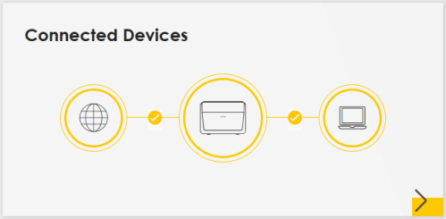
Click the Arrow icon ( ) to view IP addresses and MAC addresses of the wireless and wired devices connected to the Zyxel Device.
) to view IP addresses and MAC addresses of the wireless and wired devices connected to the Zyxel Device.Connectivity: Connected Devices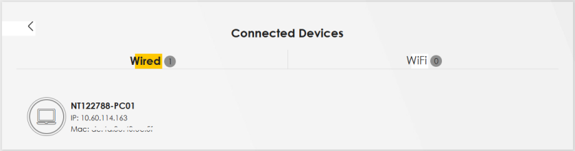
You can change the icon and name of a connected device. Place your mouse within the device block, and an Edit icon ( ) will appear. Click the Edit icon, and you will see there are several icon choices for you to select. Enter a name in the Device Name field for a connected device. Click to enable (
 ) Internet Blocking for a connected Wi-Fi client.
) will appear. Click the Edit icon, and you will see there are several icon choices for you to select. Enter a name in the Device Name field for a connected device. Click to enable () Internet Blocking for a connected Wi-Fi client.Icon and Device Name
Select an icon and/or enter a name in the Device Name field for a connected device. Click to enable ( ) Internet Blocking (or Active) for a connected Wi-Fi client. Click Save to save your changes.
) Internet Blocking (or Active) for a connected Wi-Fi client. Click Save to save your changes.Connectivity: Edit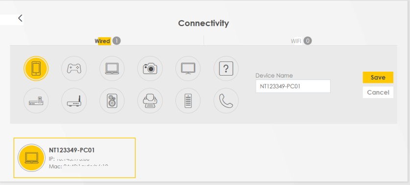
System Info
Use this screen to view the basic system information of the Zyxel Device.
System Info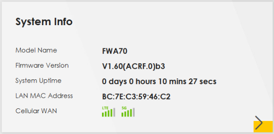
Click the Arrow icon ( ) to view more information on the status of your firewall and interfaces (WAN, LAN, and WLAN).
) to view more information on the status of your firewall and interfaces (WAN, LAN, and WLAN).System Info: Detailed Information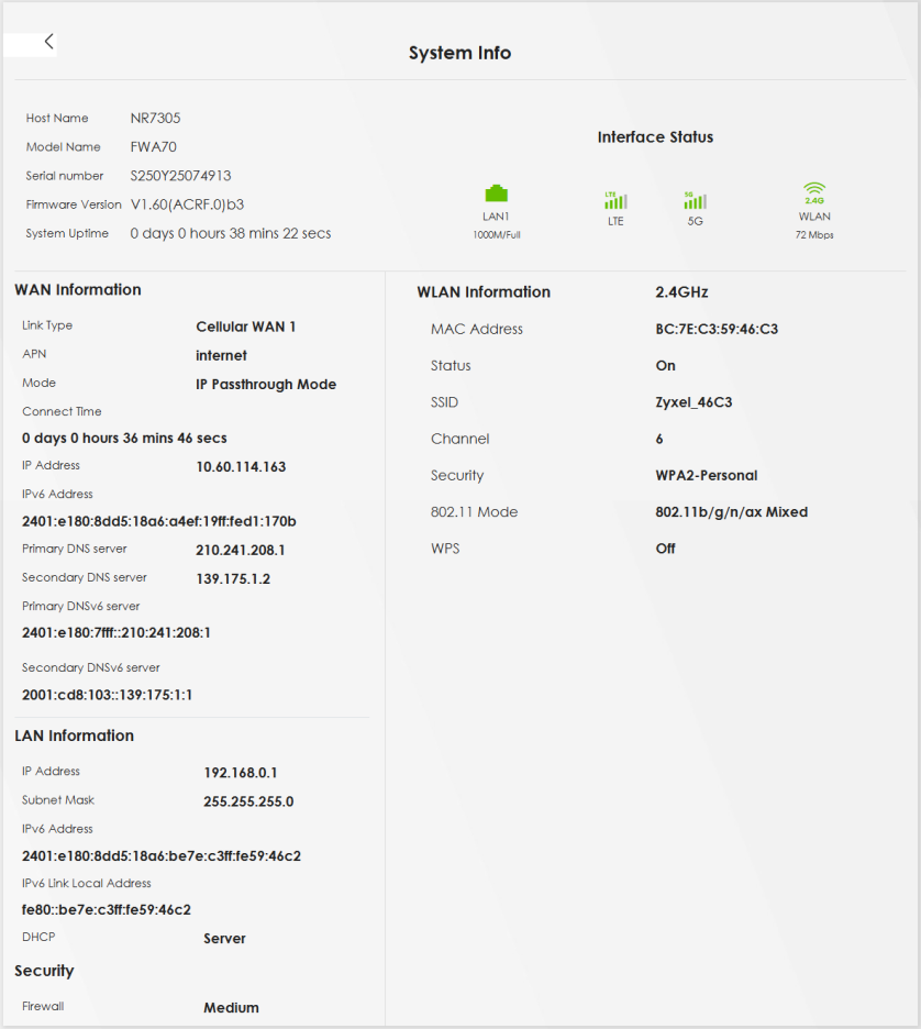
Each field is described in the following table.
LABEL | DESCRIPTION |
|---|---|
Host Name | This field displays the Zyxel Device system name. It is used for identification. |
Model Name | This shows the model number of your Zyxel Device. |
Serial Number | This field displays the serial number of the Zyxel Device. |
Firmware Version | This is the current version of the firmware inside the Zyxel Device. |
System Uptime | This field displays how long the Zyxel Device has been running since it last started up. The Zyxel Device starts up when you plug it in, when you restart it (Maintenance > Reboot), or when you reset it. |
Interface Status | Virtual ports are shown here. You can see the ports in use and their transmission rate. |
WAN Information | (These fields display when you have a WAN connection.) |
Link Type | This field displays the type of WAN connection that the Zyxel Device is currently using, such as Cellular WAN or Ethernet. |
APN | This field displays the Access Point Name (APN). |
Mode | This field displays the current mode of your Zyxel Device. |
Connect Time | This field displays the current WAN connection time. |
IP Address | This field displays the current IPv4 address of the Zyxel Device in the WAN. |
IP Subnet Mask | This field displays the current IPv4 subnet mask of the Zyxel Device in the WAN. |
IPv6 Address | This field displays the current IPv6 address of the Zyxel Device in the WAN. |
Cellular Info
Use this screen to view cellular connection information, details on signal strength that you can use as a reference for positioning the Zyxel Device. SIM card and module information is also shown in the screen.
Cellular Info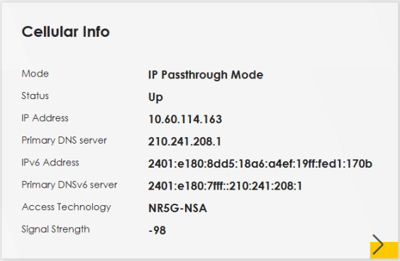
Click the Arrow icon ( ) to view the more information on the cellular connection.
) to view the more information on the cellular connection.Cellular Info: Detailed Information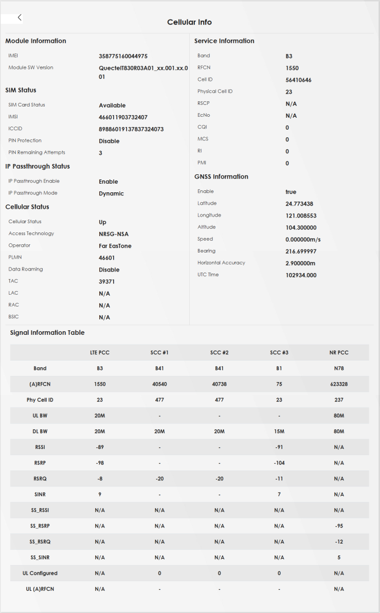
The following table describes the labels in this screen.
Label | Description |
|---|---|
Module Information | |
IMEI | This shows the International Mobile Equipment Identity of the Zyxel Device. |
Module SW Version | This shows the software version of the cellular network module. |
SIM Status | |
SIM Card Status | This displays the SIM card status: None – the Zyxel Device does not detect that there is a SIM card inserted. Waiting SIM Available – the SIM card is detected but not available yet. Available – the SIM card is detected and activated. Locked – the SIM card has PIN code security, but you did not enter the PIN code yet. Blocked – you entered an incorrect PIN code too many times, so the SIM card has been locked; call the ISP for a PUK (Pin Unlock Key) to unlock the SIM card. Error – the Zyxel Device detected that the SIM card has errors. |
IMSI | This displays the International Mobile Subscriber Identity (IMSI) of the installed SIM card. An IMSI is a unique ID used to identify a mobile subscriber in a mobile network. |
ICCID | Integrated Circuit Card Identifier (ICCID). This is the serial number of the SIM card. |
PIN Protection | A PIN (Personal Identification Number) code is a key to a SIM card. Without the PIN code, you cannot use the SIM card. Shows Enable if the service provider requires you to enter a PIN to use the SIM card. Shows Disable if the service provider lets you use the without inputting a PIN, or you disable PIN Protection in Network Setting > Broadband > Cellular SIM. |
PIN Remaining Attempts | This is how many more times you can try to enter the PIN code before the ISP blocks your SIM card. |
IP Passthrough Status | |
IP Passthrough Enable | This displays if IP Passthrough is enabled on the Zyxel Device. IP Passthrough allows a LAN computer on the local network of the Zyxel Device to have access to web services using the public IP address. When IP Passthrough is configured, all traffic is forwarded to the LAN computer and will not go through NAT. |
IP Passthrough Mode | This displays the IP Passthrough mode. This displays Dynamic and the Zyxel Device will allow traffic to be forwarded to the first LAN computer requesting an IP address from the Zyxel Device. This displays Fixed and the Zyxel Device will allow traffic to be forwarded to a specific LAN computer on the local network of the Zyxel Device. |
Cellular Status | |
Cellular Status | This displays the status of the cellular Internet connection. |
Access Technology | This displays the type of the mobile network (such as LTE, UMTS, GSM, NR5G) to which the Zyxel Device is connecting. |
Operator | This displays the name of the service provider. |
PLMN | This displays the PLMN (Public Land Mobile Network) number. |
Data Roaming | This displays if data roaming is enabled on the Zyxel Device. Data roaming is to use your Zyxel Device in an area which is not covered by your service provider. Enable roaming to ensure that your Zyxel Device is kept connected to the Internet when you are traveling outside the geographical coverage area of the network to which you are registered. |
GNSS Information Global Navigation Satellite System (GNSS) sends position and timing data from high orbit artificial satellites. It works with GPS navigational satellites to provide better receiver accuracy and reliability than just using GPS alone. This is necessary for 5G networks that require very accurate timing for time and frequency synchronization. With GNSS, your can easily locate the Zyxel Device with accurate information. | |
Enable | This shows if GNSS is enabled. Note: This can only be configured by a qualified service technician. |
Scan OnBoot | This shows Enable if Scan OnBoot is enabled, so that GNSS runs automatically after the Zyxel Device is turned on. |
Scan Status | This shows GNSS error codes for debugging by a qualified service technician. |
HDOP | Horizontal Dilution of Precision (HDOP) shows how accurate data collected by the Zyxel Device is according to the current satellite configuration. A smaller value of HDOP means a higher precision. |
Display Format | This shows the latitude and longitude display modes. There are three modes: 0, 1, and 2. Below are examples for these modes shown in latitude/longitude. 0 – ddmm.mmmmN/S, dddmm.mmmmE/W 1 – ddmm.mmmmmm, N/S, dddmm.mmmmmm, E/W 2 – (–)dd.ddddd, (–)ddd.ddddd N/S/E/W: North/South/East/West “–” : Negative values refer to South latitude/West longitude respectively. Positive values refer to North latitude/East longitude. |
Latitude | This shows the latitude coordinate of the Zyxel Device. These positioning values (latitude, longitude, and altitude) help you locate the Zyxel Device accurately. |
Longitude | This shows the longitude coordinate of the Zyxel Device. |
Elevation | This shows the measure of the Zyxel Device above mean sea level (MSL) in meters. |
Altitude | This shows the height of the Zyxel Device above mean sea level or ground level in meters. |
Positioning Mode | This shows the GNSS positioning mode. 2D (“2”) GNSS positioning mode displays latitude and longitude co-ordinates; 3D (“3”) GNSS positioning mode displays latitude and longitude co-ordinates, and elevation. |
Course over ground | This shows the course of the Zyxel Device based on true North. Course Over Ground (COG) is different from the direction an object is headed, but the path derived from its actual motion (considered as Track), since the motion of an object is often with respect to other factors like wind and tides. |
Speed | This shows the Speed Over Ground (SOG) of the Zyxel Device in meters per second (m/s). SOG is the true object speed over the surface of the Earth. |
Last Fix Time | This shows the last time in UTC format that the position of the Zyxel Device was updated. |
Number Of Satellites | This shows the number of current active satellites. GNSS requires at least 4 satellites to determine the position of the Zyxel Device. |
NR-NSA Information | |
MCC | This shows the Mobile Country Code (MCC). MCC is a unique code that identifies the country where a Public Land Mobile Network (PLMN) is at. |
MNC | This shows the Mobile Network Code (MNC). MNC is a unique code that identifies a Public Land Mobile Network (PLMN) in a country. MCC and MNC combined together are used to identify a globally unique PLMN. |
Service Information | |
Access Technology | This displays the type of the mobile network (such as LTE, UMTS, GSM) to which the Zyxel Device is connecting. |
Band | This displays the current cellular band of your Zyxel Device (WCDMA2100). |
RSSI (dBm) | This displays the strength of the cellular signal between an associated cellular station and the Zyxel Device. |
Cell ID | This shows the cell ID, which is a unique number used to identify the Base Transceiver Station to which the Zyxel Device is connecting. The value depends on the type of the mobile network (such as LTE, UMTS, GSM) to which the Zyxel Device is connecting: • For UMTS, it is the Cell Identity as defined in SIB3 3GPP-TS.25.331, 3GPP-TS.24.008. • For LTE, it is the 28-bit binary number Cell Identity as specified in SIB1 in 3GPP-TS.36.331. The value is ‘0’ (zero) or ‘N/A’ if there is no network connection. |
Physical Cell ID | This shows the Physical Cell ID (PCI), which are queries and replies between the Zyxel Device and the mobile network it is connecting to. The normal range is 1 to 504. |
UL Bandwidth (MHz) | This shows the uplink cellular channel bandwidth from the Zyxel Device to the base station. According to 3GPP specifications, the bandwidths defined by the standard are 1.4, 3, 5, 10, 15, and 20 MHz. The wider the bandwidth the higher the throughput. |
DL Bandwidth (MHz) | This shows the downlink cellular channel bandwidth from the base station to the Zyxel Device. According to 3GPP specifications, the bandwidths defined by the standard are 1.4, 3, 5, 10, 15, and 20 MHz. The wider the bandwidth the higher the throughput. |
RFCN | This displays the Radio Frequency Channel Number of DL carrier frequency used by the mobile network to which the Zyxel Device is connecting. The value depends on the type of the mobile network (such as LTE, UMTS, GSM) to which the Zyxel Device is connecting: • For UMTS (3G), it is the UARFCN (UTRA Absolute Radio-Frequency Channel Number) as specified in 3GPP-TS.25.101. • For LTE, it is the EARFCN (E-UTRA Absolute Radio-Frequency Channel Number) as specified in 3GPP-TS.36.101. The value is ‘0’ (zero) or ‘N/A’ if there is no network connection. |
RSRP (dBm) | This displays the Reference Signal Receive Power (RSRP), which is the average received power of all Resource Element (RE) that carry cell-specific Reference Signals (RS) within the specified bandwidth. The received RSRP level of the connected E-UTRA cell, in dBm, is as specified in 3GPP-TS.36.214. The reporting range is specified in 3GPP-TS.36.133. An undetectable signal is indicated by the lower limit, example –140 dBm. This parameter is for LTE only. The normal range is –44 to –140. The signal is better when the value is closer to -44. The value is –140 if the Current Access Technology is not LTE. The value is ‘N/A’ if there is no network connection. |
RSRQ (dB) | This displays the Reference Signal Receive Quality (RSRQ), which is the ratio of RSRP to the E-UTRA carrier RSSI and indicates the quality of the received reference signal. The received RSRQ level of the connected E-UTRA cell, in 0.1 dB, is as specified in 3GPP-TS.36.214. An undetectable signal is indicated by the lower limit, example –240. This parameter is for LTE only. The normal range is –30 to –240. The value is –240 if the Current Access Technology is not LTE. The value is ‘N/A’ if there is no network connection. |
RSCP | This displays the Received Signal Code Power, which measures the power of channel used by the Zyxel Device. The received signal level, in dBm, is of the CPICH channel (Ref. 3GPP TS 25.133). An undetectable signal is indicated by the lower limit, example –120 dBm. This parameter is for UMTS only. The normal range is –30 to –120. The value is –120 if the Current Access Technology is not UMTS. The value is ‘N/A’ if there is no network connection. |
EcNo | This displays the ratio (in dB) of the received energy per chip and the interference level. The measured EcNo is in 0.1 dB and is received in the downlink pilot channel. An undetectable signal is indicated by the lower limit, example –240 dB. This parameter is for UMTS only. The normal range is –30 to –240. The value is –240 if the Current Access Technology is not UMTS or there is no network connection. |
TAC | This displays the Tracking Area Code (TAC), which is used to identify the country of a mobile subscriber. The physical cell ID of the connected E-UTRAN cell, is as specified in 3GPP-TS.36.101. This parameter is for LTE only. The value is ‘0’ (zero) or ‘N/A’ if the Current Access Technology is not LTE or there is no network connection. |
LAC | This displays the 2-octet Location Area Code (LAC), which is used to identify a location area within a PLMN. The LAC of the connected cell is as defined in SIB 1 [3GPP-TS.25.331]. The concatenation of PLMN ID (MCC+MNC) and LAC uniquely identifies the LAI (Location Area ID) [3GPP-TS.23.003]. This parameter is for UMTS or GPRS. The value is ‘0’ (zero) if the Current Access Technology is not UMTS or GPRS. The value is ‘N/A’ if there is no network connection. |
RAC | This displays the RAC (Routing Area Code), which is used in mobile network “packet domain service” (PS) to identify a routing area within a location area. In a mobile network, the Zyxel Device uses LAC (Location Area Code) to identify the geographical location for the old 3G voice only service, and uses RAC to identify the location of data service like HSDPA or LTE. The RAC of the connected UTRAN cell is as defined in SIB 1 [3GPP-TS.25.331]. The concatenation of PLMN ID (MCC+MNC), LAC, and RAC uniquely identifies the RAI (Routing Area ID) [3GPP-TS.23.003]. This parameter is for UMTS or GPRS. The value is ‘0’ (zero) if the Current Access Technology is not UMTS or GPRS. The value is ‘N/A’ if there is no network connection. |
BSIC | The Base Station Identity Code (BSIC), which is a code used in GSM to uniquely identify a base station. This parameter is for GPRS only. The value is ‘0’ (zero) if the Current Access Technology is not GPRS. The value is ‘N/A’ if there is no network connection. |
SINR (dB) | This displays the Signal to Interference plus Noise Ratio (SINR) in dB. This is also a measure of signal quality and used by the UE (User Equipment) to calculate the Channel Quality Indicator (CQI) that it reports to the network. A negative value means more noise than signal. |
CQI | This displays the Channel Quality Indicator (CQI). It is an indicator carrying the information on how good or bad the communication channel quality is. |
MCS | MCS stands for modulation coding scheme. The base station selects MCS based on current radio conditions. The higher the MCS the more bits can be transmitted per time unit. |
RI | This displays the Rank Indication, one of the control information that a UE will report to eNodeB (Evolved Node-B) on either PUCCH (Physical Uplink Control Channel) or PUSCH (Physical Uplink Shared Channel) based on uplink scheduling. |
PMI | This displays the Precoding Matrix Indicator (PMI). PMI is for transmission modes 4 (closed loop spatial multiplexing), 5 (multi-user MIMO), and 6 (closed loop spatial multiplexing using a single layer). PMI determines how cellular data are encoded for the antennas to improve downlink rate. |
SCC Information | If the cellular service provider supports carrier aggregation (CA), then this section displays statistics for the connection’s secondary component carriers (SCCs). |
# | This displays the ID of the SCC. Some cellular providers support two or more SCCs. |
NR Physical Cell ID | This displays the Physical Cell ID (PCI) of the SCC. |
UL Bandwidth (MHz) | This shows the uplink cellular channel bandwidth from the Zyxel Device to the base station. According to 3GPP specifications, the bandwidths defined by the standard are 1.4, 3, 5, 10, 15, and 20 MHz. The wider the bandwidth the higher the throughput. |
DL Bandwidth (MHz) | This shows the downlink cellular channel bandwidth from the base station to the Zyxel Device. According to 3GPP specifications, the bandwidths defined by the standard are 1.4, 3, 5, 10, 15, and 20 MHz. The wider the bandwidth the higher the throughput. |
RFCN | This displays the Radio Frequency Channel Number of DL carrier frequency used by the SCC. |
Band | This displays the current cellular band used by the SCC. |
RSSI | This displays the cellular signal strength between an associated cellular station and the Zyxel Device for this SCC. |
NR RSRP | This displays the Received Signal Code Power of the SCC. |
NR RSRQ | This displays the Reference Signal Receive Quality of the SCC. |
NR SINR (dBm) | This displays the Signal to Interference plus Noise Ratio (SINR) of the SCC. |
TAC | This displays the Tracking Area Code (TAC), which is used to identify the country of a mobile subscriber. The physical cell ID of the connected E-UTRAN cell, is as specified in 3GPP-TS.36.101. This parameter is for LTE only. The value is ‘0’ (zero) or ‘N/A’ if the Current Access Technology is not LTE or there is no network connection. |
Nebula Control Center Status
Use this screen to enable or disable Nebula Discovery. You can also view the Internet connection status, Nebula connection status and the Zyxel Device registration status in this screen.
Nebula Control Center Status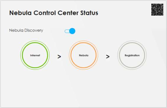
When the Zyxel Device is being managed by NCC, the Nebula Control Center Status will appear as follows.
Nebula Control Center Status – NCC Managed 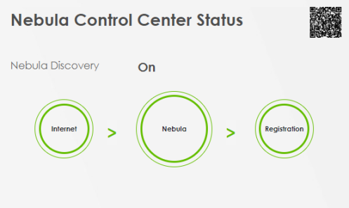
Each field is described in the following table.
LABEL | DESCRIPTION |
|---|---|
Nebula Discovery | Enable this to have the Zyxel Device connect to the NCC and change to the NCC management mode if the Zyxel Device is connected to the Internet and has been registered on the NCC. This is not configurable and will only display ON when your Zyxel Device is being managed by NCC. |
Nebula Control Center Status | This field displays: • The Zyxel Device Internet connection status. • The connection status between the Zyxel Device and the NCC. • The Zyxel Device registration status on the NCC. Mouse over the circles to display detailed information. To pass your Zyxel Device management to the NCC, make sure your Zyxel Device is connected to the Internet. Then go to the NCC and register your Zyxel Device. Internet • Green: The Zyxel Device is connected to the Internet. • Orange: The Zyxel Device is not connected to the Internet. Nebula • Green: The Zyxel Device is connected to the NCC. • Gray: The Zyxel Device is not connected to the NCC. Registration • Green: The Zyxel Device is registered on the NCC. • Gray: The Zyxel Device is not registered on the NCC. Please note that all circles will gray out if you disable Nebula Discovery. When a circle is gray or orange, hover the mouse over the circle to check the diagnostic message. |
QR Code | Click on the QR code icon at the top right corner to show the QR code you can use to register the Zyxel Device on the NCC using the Nebula Mobile app. |
Wi-Fi Settings
The following compares the main Wi-Fi network and the guest Wi-Fi network.
feature | main wi-fi | guest wi-fi |
|---|---|---|
Purpose | For primary household or business users. | For visitors. |
Network Access | For access to internal devices, such as printers or file servers. | Internet access only; no access to internal devices. |
Use this screen to enable or disable the main Wi-Fi network. When the switch turns blue, the function is enabled. You can use this screen or the QR code on the upper right corner to check the SSIDs (Wi-Fi network name) and passwords of the main Wi-Fi networks. If you want to show or hide your Wi-Fi passwords, click the Eye icon ( ).
).
).Wi-Fi Settings (for 2.4 GHz and 5 GHz models)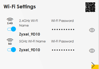
Click the Arrow icon ( ) to configure the SSIDs and/or passwords for your main Wi-Fi networks. Click the Eye icon (
 ) to display the characters as you enter the Wi-Fi Password.
) to configure the SSIDs and/or passwords for your main Wi-Fi networks. Click the Eye icon () to display the characters as you enter the Wi-Fi Password.Scanning the QR code is an alternative way to connect your Wi-Fi client to the Wi-Fi network.
Select Keep 2.4G and 5G the same to use the same SSID for 2.4 GHz and 5 GHz bands.
Wi-Fi Settings: Configuration (for 2.4 GHz and 5 GHz models)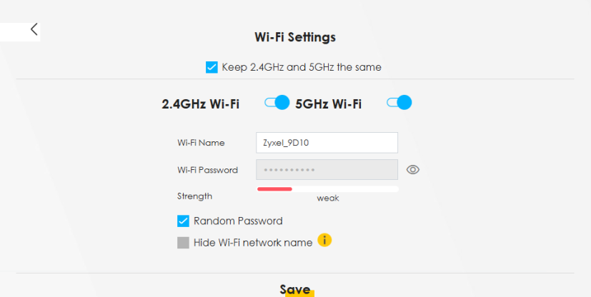
Each field is described in the following table.
LABEL | DESCRIPTION |
|---|---|
2.4 GHz or 5 GHz Wi-Fi | Click this switch to enable or disable the 2.4 GHz or 5 GHz Wi-Fi networks. When the switch goes to the right  , the function is enabled. Otherwise, it is not. , the function is enabled. Otherwise, it is not. |
Wi-Fi Name | The SSID (Service Set IDentity) identifies the service set with which a wireless device is associated. Wireless devices associating to the access point (AP) must have the same SSID. Enter a descriptive name (up to 32 printable characters, including spaces) for the Wi-Fi. |
Wi-Fi Password | If you selected Random Password, this field displays a pre-shared key generated by the Zyxel Device. If you did not select Random Password, you can manually enter a pre-shared key from 8 to 64 alphanumeric (0-9, a-z, A-Z) and special characters, including spaces. |
Wi-Fi Password | Click the Eye icon to show or hide the password of your Wi-Fi network. When the Eye icon is slashed  , you will see the password in plain text. Otherwise, it is hidden. , you will see the password in plain text. Otherwise, it is hidden. |
Strength | This displays the current password strength – weak, medium, strong. |
Random Password | Select this option to have the Zyxel Device automatically generate a password. The Wi-Fi Password field will not be configurable when you select this option. |
Hide Wi-Fi network name | Select this checkbox to hide the SSID in the outgoing beacon frame so a station cannot obtain the SSID through scanning using a site survey tool. |
Save | Click Save to save your changes. |
More AP Wi-Fi Settings
Use this screen to enable or disable the guest 2.4 GHz / 5 GHz Wi-Fi networks. When the switch goes to the right ( ), the function is enabled. Otherwise, it is not. You can check their SSIDs (Wi-Fi network name) and passwords from this screen. If you want to show or hide your Wi-Fi passwords, click the Eye icon.
), the function is enabled. Otherwise, it is not. You can check their SSIDs (Wi-Fi network name) and passwords from this screen. If you want to show or hide your Wi-Fi passwords, click the Eye icon.More AP Wi-Fi Settings (for 2.4 GHz and 5 GHz models)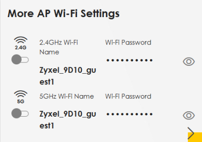
Click the Arrow icon ( ) to open the following screen. Use this screen configure the SSIDs and/or passwords for your More AP Wi-Fi networks.
) to open the following screen. Use this screen configure the SSIDs and/or passwords for your More AP Wi-Fi networks.To assign different SSIDs to the 2.4 GHz and 5 GHz guest wireless networks, clear the Keep 2.4GHz and 5GHz the same checkbox in the Wi-Fi Settings screen, and the More AP Wi-Fi Settings screen will change.
Guest Wi-Fi Settings: Configuration (for 2.4G and 5G models)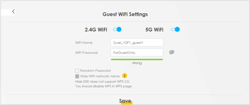
More AP Wi-Fi Settings: Different SSIDs (for 2.4 GHz and 5 GHz models)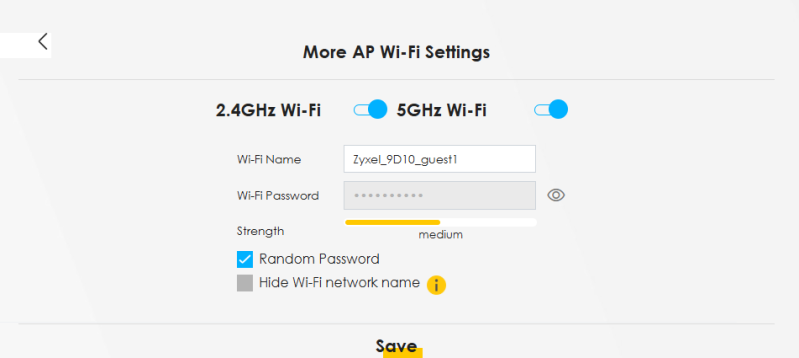
Each field is described in the following table.
LABEL | DESCRIPTION |
|---|---|
2.4GHz or 5GHz Wi-Fi | Click this switch to enable or disable the 2.4 GHz or 5 GHz Wi-Fi networks. When the switch goes to the right  , the function is enabled. Otherwise, it is not. , the function is enabled. Otherwise, it is not. |
Wi-Fi Name | The SSID (Service Set IDentity) identifies the service set with which a wireless device is associated. Wireless devices associating to the access point (AP) must have the same SSID. Enter a descriptive name (up to 32 printable characters, including spaces) for the Wi-Fi. |
Wi-Fi Password | If you selected Random Password, this field displays a pre-shared key generated by the Zyxel Device. If you did not select Random Password, you can manually enter a pre-shared key from 8 to 64 alphanumeric (0-9, a-z, A-Z) and special characters, including spaces. Click the Eye icon to show or hide the password of your Wi-Fi network. When the Eye icon is slashed  , you will see the password in plain text. Otherwise, it is hidden. , you will see the password in plain text. Otherwise, it is hidden. |
Strength | This displays the current password strength – weak, medium, strong. |
Random Password | Select this option to have the Zyxel Device automatically generate a password. The Wi-Fi Password field will not be configurable when you select this option. |
Hide Wi-Fi network name | Select this checkbox to hide the SSID in the outgoing beacon frame so a station cannot obtain the SSID through scanning using a site survey tool. |
Save | Click Save to save your changes. |
LAN
Use this screen to view the LAN IP address, subnet mask, and DHCP settings of your Zyxel Device. Click the switch button to turn on/off the DHCP server.
LAN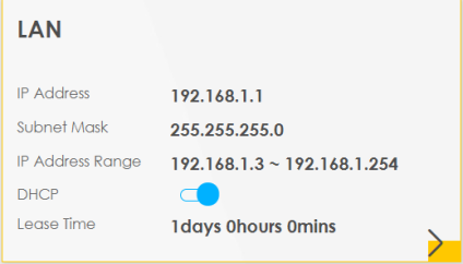
Click the Arrow icon ( ) to configure the LAN IP settings and DHCP setting for your Zyxel Device.
) to configure the LAN IP settings and DHCP setting for your Zyxel Device.LAN Setup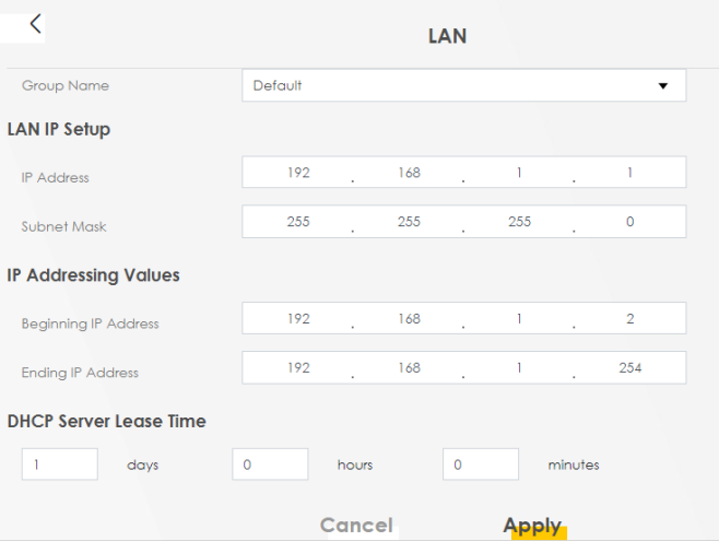
Each field is described in the following table.
LABEL | DESCRIPTION |
|---|---|
Group Name | Select the interface group you want to use. Usually Default. |
LAN IP Setup | |
IP Address | Enter the LAN IPv4 IP address you want to assign to your Zyxel Device in dotted decimal notation, for example, (factory default). |
IP Address | Enter the LAN IPv4 IP address you want to assign to your Zyxel Device in dotted decimal notation, for example, 192.168.15.1 (factory default). |
Subnet Mask | Enter the subnet mask of your network in dotted decimal notation, for example 255.255.255.0 (factory default). Your Zyxel Device automatically computes the subnet mask based on the IP Address you enter, so do not change this field unless you are instructed to do so. |
IP Addressing Values | |
Beginning IP Address | This field specifies the first of the contiguous addresses in the IP address pool. |
Ending IP Address | This field specifies the last of the contiguous addresses in the IP address pool. |
DHCP Server State | |
DHCP Server Lease Time | This is the period of time a DHCP-assigned address is valid, before it expires. When a client connects to the Zyxel Device, DHCP automatically assigns the client an IP addresses from the IP address pool. DHCP leases each addresses for a limited period of time, which means that past addresses are “recycled” and made available for future reassignment to other devices. |
Days/Hours/Minutes | Enter the lease time of the DHCP server. |
Save | Click Save to save your changes. |
Apply | Click Apply to save your changes. |
Cancel | Click Cancel to restore your previously saved settings. |