Wireless
Overview
Use the Wireless screens to configure how the Zyxel Device manages supported Access Points (APs). Supported APs should be in managed mode.
What You Can Do in this Chapter
• Use the AP Control Service screen (The AP Control Service Screen) to set the password for the admin accounts of APs connected to the Zyxel Device.
• Use the AP List screen (The AP List Screen) to manage all of the APs connected to the Zyxel Device.
• Use the Policy screen (The Policy Screen) to configure the AP controller’s IP address on the managed APs and determine the action the managed APs take if the current AP controller fails.
• Use the AP Firmware screen (The AP Firmware Screen) to check for and download new AP firmware when it becomes available on the firmware server.
• Use the WLAN Clients screen (The WLAN Clients Screen) to view a list of WiFi clients connected to APs.
• Use the SSID Settings screen (The SSID Settings Screen) to configure up to 8 different SSID profiles for each AP group.
• Use the Radio Settings screen (The Radio Settings Screen) to configure global radio settings for all managed APs.
• Use the AP Settings screen (The AP Settings Screen) to configure general AP settings and enable or disable a port on the managed AP and configure the port’s VLAN settings.
• Use the AP Group Settings screen (The AP Group Settings Screen) to configure AP group settings and remove an AP group.
• Use the Wireless Health screen (The Wireless Health Screen) to monitor the health of WiFi networks for your APs and connected WiFi clients.
What You Need to Know
Supported APs
At the time of writing, the following APs can be managed by the Zyxel Device.
• WAC500H | • WAX650S | • WBE530 |
• WAX300H | • WAX655E | • WBE630S |
• WAX510D | • WAX620D-6E | • WBE660S |
• WAX610D | • WAX640S-6E | |
• WAX630S | • WBE510D |
WiFi 6 (IEEE 802.11ax)
WiFi 6 (802.11ax) is a WiFi standard that supports both 2.4GHz and 5GHz frequency bands and brings the following major improvements:
High Data Transmission Speed
WiFi 6 provides faster transmission data rate than its previous WiFi standards with the following features:
• 1024-QAM (Quadrature Amplitude Modulation)- enhances the data capacity of each transmission unit.
• 160 MHz Channel Bandwidth- extends the supported channel bandwidth to 160 MHz, providing higher data throughput.
Enhanced Air Time Utilization
WiFi 6 increases transmission performance in high-density environments that have multiple client devices with the following features:
• OFDMA (Orthogonal Frequency-Division Multiple Access)- divides channels into sub-channels that enables multiple transmissions in a single channel.
• BSS Coloring- tags traffic by BSS (Basic Server Set) and identifies traffic from overlapping BSSs. The AP can ignore traffic of unrelated BSSs and transmit data when a channel is occupied.
• MU-MIMO (Multiple User-Multiple Input Multiple Output)- enables multiple users to connect to the AP and download/upload traffic simultaneously.
Extended Signal Range
Beamforming forms the radiating signals into one direction. This enhances the signal strength and extends the signal transmission range.
Extended Battery Life
Target Wake Time (TWT) allows the AP to negotiate with client devices so client devices only wakes up and communicates with the AP in specific periods. This conserve client devices battery life.
WiFi 6E (IEEE 802.11ax - Extended Standard)
WiFi 6E is an extended standard of WiFi 6 (IEEE 802.11ax). WiFi 6E inherits all the WiFi 6 features and brings with an additional 6 GHz band. The 6 GHz band allows you to avoid possible congested traffic in the lower 2.4 GHz and 5 GHz bands. WiFi clients must support WiFi 6E to connect to an AP using the 6 GHz band.
You must use WPA3 for security with WiFi 6E.
WiFi 6E MBSSID Beacon Management
The AP supports MBSSID, which allows you to create multiple virtual WiFi networks (SSIDs) on the AP. With the WiFi 6E (802.11ax-extended) standard, the AP divides SSIDs into groups, and includes information of all SSIDs in a group in one SSID beacon. Therefore, the Zyxel Device doesn’t need to send beacons for individual SSIDs, which improves air time efficiency.
Out-of-Band Discovery
Out-of-band discovery allows the AP to include information of the 6 GHz band in management frames sent over the 2.4 GHz /5 GHz bands. WiFi 6E clients only need to scan the lower bands (2.4 GHz/5 GHz) to connect to the AP in the 6 GHz band, reducing the discovery time.
PSC Channel (In-Band Discovery)
PSCs (Preferred Scanning Channels) are dedicated channels for WiFi 6E clients to send probe requests on to discover a compatible AP, instead of scanning the entire 6 GHz band. In this way, WiFi 6E clients are able to efficiently discover and connect to the AP within the 6 GHz band.
Resource Unit
A resource unit is a portion of a channel bandwidth. For example, a 20 MHz channel can be divided into several resource units. Each resource unit can be allocated to a specified WiFi client, allowing simultaneous data transmission.
WiFi 7 (IEEE802.11be)
WiFi 7 (802.11be) is backward-s compatible with WiFi 6 and WiFi 6E. WiFi 7 is a WiFi standard that supports 2.4 GHz, 5 GHz and 6 GHz frequency bands with the following improvements over WiFi 6 and WiFi 6E.
Features | WiFi 6 | Wifi 6e | WiFi 7 | |
|---|---|---|---|---|
Theoretical Maximum Speed (Up-to) | 9.6 Gbps | 46 Gbps | ||
Supported Frequency Bands | 2.4 GHz/5 GHz | 2.4 GHz/5 GHz/6 GHz | 2.4 GHz/5 GHz/6 GHz | |
Supported Channel Bandwidth | 20/40/80/160 MHz | 20/40/80/160 MHz | 20/40/80/160/320 MHz | |
Total Spectrum (Up-to) | 2.4 GHz | 80 MHz | 80 MHz | |
5 GHz | 500 MHz | 500 MHz | ||
6 GHz | Not supported. | 1200 MHz | 1200 MHz | |
Other Features (OFDMA/BSS Coloring/TWT/Two-Way MU-MIMO/Beamforming/1024-QAM) | The same (WiFi 6E inherits all the features from WiFi 6). | WiFi 7 inherits all the features from WiFi 6 and WiFi 6E, with the addition of multi-link operation and preamble puncturing. | ||
Faster Data Transmission
WiFi 7 allows faster data transmission using:
• 4096 QAM (Quadrature Amplitude Modulation)- enhances the amount of data transmitted over the available bandwidth.
• 320 MHz Channel Bandwidth- enlarges the supported channel bandwidth to 320 MHz, allowing higher data throughput.
• Multiple Resource Units (RUs)- allows an AP to allocate multiple RUs to a WiFi client.
Multi-Link Operation (MLO)
An AP can support multiple frequency bands (2.4 GHz, 5 GHz and 6 GHz), but a WiFi client can only connect to the AP using one of these frequency bands. The other frequency bands are unused. The client's data transmission speed depends on the frequency band they are connected to.
WiFi 7 MLO allows a WiFi client to connect to the AP using multiple frequency bands simultaneously. This increases speed and improves reliability of the WiFi connection. MLO makes WiFi 7 ideal for streaming 4K/8K videos, using augmented reality (AR), virtual reality (VR) applications and playing online games.
To use MLO, both the AP and the WiFi client have to support MLO.
Preamble Puncturing
In WiFi 6 and earlier, any interference would cause the entire WiFi channel to become unavailable. In the figure below, if part of the WiFi channel (B) experiences interference, the rest of the WiFi channel (C) becomes unavailable.
Without Preamble Puncturing
WiFi 7 preamble puncturing allows you to block the specific portion of the channel that is experiencing interference while continuing to use the rest of the WiFi channel. In the figure below, if part of the WiFi channel (B) experiences interference, the rest of the WiFi channel (C) is still available.
Preamble Puncturing Example
AP Group
AP group (Access Point group) allows you to organize multiple APs into a single group. You can use an AP group to manage multiple APs at once, instead of configuring each AP individually. WiFi clients in a same AP group can move between without losing connection or needing to re-authenticate. To create an AP group:
1 Go to Wireless > WLAN Settings. Clink Add from the AP Group drop-down list to add an AP group.
2 Go to Wireless > Access Points > AP List. Select the APs you want to add to the AP group.
3 Click More > Move to Group.
4 Select the AP group you want the selected APs join. Click Apply.
SSID Broadcast Control Using AP and SSID Tags
When managing a large number of APs, you can use tags to control SSID broadcast from specific APs. When the tags of an SSID and an AP in the same group match, the SSID will be broadcast.
An SSID is a WiFi network name. An AP may have several unique SSIDs. An AP broadcasts SSIDs for WiFi clients to join.
• You can assign multiple tags to APs that are in the same AP group (Wireless > Access Points > AP List > Managed AP > Edit AP)
• You can then assign an AP tag or multiple AP tags to an SSID. (Wireless > WLAN Settings > SSID Settings > Advanced)
• When an SSID has an AP tag, only APs (in the same AP group) with that tag will broadcast that SSID for WiFi clients to join. APs that do not have that tag will not broadcast that SSID.
• If you do not assign an AP tag to an SSID, then only the AP with that SSID will broadcast the SSID.
The advantage of tags is that you can have multiple APs broadcast the same SSID to easily allow roaming within the same AP group coverage area.
Application Scenario
• AP1 has tags 1F, 2F, 3F with SSID1, SSID2, SSID3
• AP2 has tags 3F, 4F with SSID1, SSID2, SSID3
• AP3 has tags 4F, 5F with SSID1, SSID2, SSID3
• You assign AP tag 3F to SSID1. Therefore AP1 and AP2 will broadcast SSID1. AP3 will not broadcast SSID1.
• You assign AP tag 4F to SSID2. Therefore AP2 and AP3 will broadcast SSID2. AP1 will not broadcast SSID2.
• You do not assign an AP tag to SSID3. Therefore AP1, AP2 and AP3 will each broadcast SSID3.
AP Name | AP1 | AP2 | AP3 |
AP Tag | 1F, 2F, 3F | 3F, 4F | 4F, 5F |
SSID1 (3F) | V | V | X |
SSID2 (4F) | X | V | V |
SSID3 (no tag) | V | V | V |
Airtime Fairness
Airtime is the time it takes for a client to receive packets from the AP it is associated with. The amount of time each client needs may vary depending on various reasons, such as the distance between the client and the AP, the client’s operating system, or the IEEE standard the client is using.
Airtime fairness is a feature that makes sure all connected clients of an AP get the same amount of time to receive packets. Without airtime fairness, a client that needs more airtime will take up more time and bandwidth of an AP to receive packets. This will slow down your WiFi network overall.
For example, you have computer A and computer B at your house. They’re both connected to the same AP. Here are the conditions in the scenario examples below:
• The example time period is 60 milliseconds.
• Computer A needs 5 milliseconds to receive a packet from the AP.
• Computer B needs 10 milliseconds to receive a packet from the AP.
Airtime Fairness Disabled
Computer A and computer B will take turn to receive packets from the AP. With airtime fairness disabled, the AP will not equally allocate the 60 milliseconds between A and B.
packets received | a | b |
|---|---|---|
1 packet | 10ms | |
1 packet | 5ms | |
1 packet | 10ms | |
1 packet | 5ms | |
1 packet | 10ms | |
1 packet | 5ms | |
1 packet | 10ms | |
1 packet | 5ms | |
Total Packets Received: 8 | Total Time Period: 60ms | |
A has 20 milliseconds to receive packets. B has 40 milliseconds to receive packets. In total, they can receive 8 packets in 60 milliseconds.
Airtime Fairness Enabled
With airtime fairness enabled, the AP will equally allocate the 60 milliseconds between computer A and computer B. After B uses 10 milliseconds to receive a packet, the AP will also allocate10 milliseconds to A to receive packets.
packets received | a | b |
|---|---|---|
1 packet | 10ms | |
1 packet | 5ms | |
1 packet | 5ms | |
1 packet | 10ms | |
1 packet | 5ms | |
1 packet | 5ms | |
1 packet | 10ms | |
1 packet | 5ms | |
1 packet | 5ms | |
Total Packets Received: 9 | Total Time Period: 60ms | |
A and B both have 30 milliseconds to receive packets. In total, they can receive 9 packets in 60 milliseconds.
Uplink and Downlink
For the Zyxel Device, connections to the (root) AP are downlink. For the (root) AP, connections to the Zyxel Device are uplink, and connections to other APs further away from the Zyxel Device are downlink.
• The Zyxel Device establishes a network with Root AP (RA) and AP1. The Zyxel Device sends traffic to RA through its downlink port (DLP). RA receives that traffic through its uplink port (ULP). RA then extends the network to AP1.
• In this scenario, Zyxel Device is the uplink device of RA. RA is a downlink device of Zyxel Device and a uplink device of AP1. AP1 is a downlink device of RA.
The AP Control Service Screen
The Wireless > AP Control Service screen allows you to change the password for all accounts with the username "admin" on APs listed in the managed AP list. View the managed AP list in Wireless > Access Points > AP List.
The following table describes the labels in this screen.
label | description |
|---|---|
AP Management Service | |
Enable | Click the switch to the right to change the password for accounts with the username “admin” on the managed APs. |
AP Login Password | Set the password for accounts with the username “admin” on the managed APs. You can use 4 to 63 alphanumeric characters. The following special characters are allowed: ~!@#$%^&*()_-+={}|;:<>,./" |
Retype to Confirm | Enter the password again for confirmation. |
Cancel | Click Cancel to return the screen to its last-saved settings. |
Apply | Click Apply to save your changes back to the Zyxel Device. |
The AP List Screen
To ensure the AP you want to manage appears on the AP list:
• Make sure the AP connected to the Zyxel Device is in the same subnet as the Zyxel Device.
• Make sure the AP is in Controller Managed mode. If not, reset the AP. On your first login, the following screen appears, select Controller Managed mode.
The AP List > Managed AP Screen
Use this screen to view the managed APs.
The following table describes the labels in this screen.
label | description |
|---|---|
AP Group | Select the group of APs you want to display. You can create or remove an AP group in Wireless > WLAN Settings > SSID Settings > AP Group Settings. |
Managed AP | The APs managed by the Zyxel Device appear here. |
Edit | Double-click an entry or select it and click Edit to open a screen where you can modify the entry’s settings. |
Reboot | Select one or multiple APs and click this button to force the AP(s) to restart. |
DCS Now | Select one or multiple APs and click this button to use DCS (Dynamic Channel Selection) to allow the AP to automatically find a less-used channel in an environment where there are many APs and there may be interference. |
Query Controller Log | Select one or multiple APs and click this button to go to the Log & Report > Log/Events > AP screen to view the selected AP’s current log messages. |
Upgrade | Select one or more APs and click this button to update the APs’ firmware version. |
Nebula | Select an AP and click this to open a screen where you can set whether the AP’s IP address and VLAN settings will be changed when it goes into Nebula cloud management mode. |
Remove | Select one or multiple APs and click this button to remove the AP(s) from the manged AP list. |
Move to Group | Select an AP and click this button to change the AP group it belongs to. |
Suppression On | Select an AP and click this button to enable the AP’s LED suppression mode. All the LEDs of the AP will turn off after the AP is ready. This button is not available if the selected AP doesn’t support suppression mode. |
Suppression Off | Select an AP and click this button to disable the AP’s LED suppression mode. The AP LEDs stay lit after the AP is ready. This button is not available if the selected AP doesn’t support suppression mode. |
Locator On | Select an AP and click this button to run the locator feature. The AP’s Locator LED will start to blink for 10 minutes by default. It will show the actual location of the AP between several devices on the network. |
Smart Mesh Reconnect | Select an AP and click this button to make the AP look for and connect to another uplink AP with a stronger signal. Smart Mesh is a WiFi mesh solution for APs. With Smart Mesh, you can have two or more APs automatically create a mesh network within your home or office, ensuring there are no areas with a weak WiFi signal. |
Tag | Select an AP group from the AP Group drop-down list first. Select one or more APs and click this button to manage their tags. You can add or remove one or more tags at once to the selected AP(s) using the Append and Remove drop-down lists. You can assign up to 32 tags to one AP. You can also create new tags. A tag name can contain 1–32 single-byte characters, including [A–Z], [a–z], [0–9], [@#-_]. |
Firmware Status | This shows whether the firmware installed on the AP is up-to-date. |
Status | This shows the status of AP. • Online: APs that are online now. • Conflict: APs with configurations in conflict with the Zyxel Device (see More Details). • Non Support: APs with features not supported by the Zyxel Device (see More Details). • Updating: APs that are have updated firmware and rebooted. • Offline: The CAPWAP server did not receive keep-alive packets from these APs in the last 2 minutes (Offline All - Offline for Firmware Update). • Offline Update: APs that were rebooted before updating firmware. |
Name | This shows the descriptive name of the AP. |
IP Address | This shows the IP address of the AP. |
Model | This shows the model number of the AP. |
Station 2.4GHz | This shows the number of 2.4G wireless clients connected to the AP. |
Station 5GHz | This shows the number of 5G wireless clients connected to the AP. |
Station 6GHz | This shows the number of 6G wireless clients connected to the AP. |
Current Client | This shows how many clients are currently connecting to the AP. |
MAC Address | This shows the MAC address of the AP. |
2.4GHz | This shows the number of WiFi clients in the 2.4 GHz band. |
5GHz | This shows the number of WiFi clients in the 5 GHz band. |
6GHz | This shows the number of WiFi clients in the 6 GHz band. |
Channel Utilization 2.4GHz | This shows the percentage of the 2.4 GHz channel ID usage. |
Channel Utilization 5GHz | This shows the percentage of the 5 GHz channel ID usage. |
Channel Utilization 6GHz | This shows the percentage of the 6 GHz channel ID usage. |
Transmit Power 2.4GHz | This shows the current transmitting power of the connected AP’s 2.4 GHz band. |
Transmit Power 5GHz | This shows the current transmitting power of the connected AP’s 5 GHz band. |
Transmit Power 6GHz | This shows the current transmitting power of the connected AP’s 6 GHz band. |
% Usage | This shows the percentage of the AP’s data usage. |
Serial Number | This shows the serial number of the AP. |
Recent On-line Time | This shows the most recent time the AP came on-line. N/A shows if the AP has not come on-line since the Zyxel Device last started up. |
Hop | This shows how many APs away the AP is from the Root AP. (the AP connected to the Zyxel Device). For example, a value of 1 indicates the AP is the first AP after the root AP, while 2 indicates there is one AP between the AP and the root AP. This field is blank when the AP is the root AP. |
Uplink AP | This shows the name of the uplink AP connected to the AP. See Uplink and Downlink for the definition of uplink. |
Uplink Signal | This shows the signal strength the AP receives from the uplink AP. |
Uplink Tx/Rx Rate | This shows the maximum transmission/reception rate of the uplink AP to which the AP is connected. |
Wireless Bridge | This shows whether wireless bridge is enabled on the AP. Wireless bridge enables two devices to automatically bridge two network segments through a WiFi connection. When enabled, the system will automatically create VLAN and bridge interfaces based on the Allowed VLANs you configure below. The Zyxel Device can continue data transmission through its Ethernet port(s) even after the smart-mesh link is established. |
Uplink | This shows the frequency band the AP uses to connect to the uplink AP. |
Mgnt. VLAN ID (AC/AP) | This shows the Access Controller (the Zyxel Device) and runtime management VLAN ID setting for the AP. VLAN Conflict shows if the AP’s management VLAN ID does not match the Mgnt. VLAN ID(AC). This shows n/a if the Zyxel Device cannot get VLAN information from the AP. |
Last Off-line Time | This shows the date and time that the AP was last logged out. |
Ethernet Uplink | This shows whether the AP is connected to the gateway through a wired Ethernet APconnection or WiFi connection. |
Power Mode | This shows the AP’s power status. The AP receives power using a power adapter and/or through a PoE switch/injector. • Full – the AP receives power using IEEE 802.3at PoE plus. The PoE device that supports IEEE 802.3at PoE Plus can supply power of up to 30W per Ethernet port. When the AP’s power mode is Limited, the AP throughput decreases and has just one transmitting radio APchain. • Limited – the AP receives power using IEEE 802.3af PoE even when it is also connected to a power source using a power adapter. The PoE device that supports IEEE 802.3af PoE can supply power of up to 15.4W per Ethernet port. It always shows Full if the AP does not support power detection. |
Current Version | This shows the AP’s current firmware version. |
Group | This shows the name of the AP group to which the AP belongs. |
LED | This shows the AP LED status. • N/A shows if the AP does not support LED suppression mode and/or have a locator LED to show the actual location of the AP. • A gray LED icon signifies that the AP LED suppression mode is enabled. All the LEDs of the AP will turn off after the AP is ready. • A green LED icon signifies that the AP LED suppression mode is disabled and the AP LED stay lit after the AP is ready. • A sun icon signifies that the AP’s locator LED is blinking. • A circle signifies that the AP’s locator LED is extinguished. |
Tag | This shows the tag(s) assigned to the AP. |
Bluetooth | This shows the AP’s Bluetooth Low Energy (BLE) capability. Bluetooth Low Energy, which is also known as Bluetooth Smart, transmits less data over a shorter distance and consumes less power than classic Bluetooth. APs communicate with other BLE enabled devices using advertisements. • N/A shows if the AP does not support BLE. • Unavailable shows if the AP supports Bluetooth, but there is no BLE USB dongle connected to the USB port of the AP. Some APs, such as the WAC5302D-S, need to have a supported BLE USB dongle attached to act as a beacon to broadcast packets. • Available shows if the AP supports Bluetooth, detects a BLE device and advertising is inactive. • Advertising shows if the AP supports Bluetooth, detects a BLE device and advertising is activated, which means the BLE device can broadcasts packets to every device around it. |
Location | This shows the AP’s location you configured. |
System Name | This shows the system name to identify the AP on a network. |
Load Balancing Group | AP load balancing lets the Zyxel Device distribute WiFi clients and traffic across APs connected to the Zyxel Device to prevent overloading of APs with higher loads and lower signal quality. This shows the load balancing group name to which this AP belongs. An AP can belong to up to two load balancing groups. APs in the same load balancing group within an AP group share the client load. |
The AP List > Unmanaged AP Screen
Use this screen to view the unmanaged APs detected by the Zyxel Device.
The following table describes the labels in this screen.
label | description |
|---|---|
Unmanaged AP | The APs connected to and detected by the Zyxel Device appear here. To have the Zyxel Device manage an AP, select it and click Add to Managed AP List. |
Add to Managed AP List | Select an AP and click this to add the selected AP to the managed AP list. |
Name | This shows the descriptive name of the AP. |
IP Address | This shows the global (WAN) IP address of the AP. |
Model | This shows the model number of the AP. |
MAC Address | This shows the MAC address of the AP. |
Edit AP List
This screen allows you to configure AP’s settings.
Storm Control
Storm control prevents broadcast/multicast storms on AP interfaces. A broadcast/multicast storm occurs when broadcast/multicast packets flood devices in the same subnet, creating excessive traffic and degrading network performance.
When storm control is enabled on the Zyxel Device, the AP monitors packets received on the its interface and determines whether the packets are broadcast or multicast. The AP monitors the number of broadcast packets received within a one-second time interval. When the interface maximum packets per second threshold is met, incoming data traffic on the AP interface is dropped until the maximum packets per second falls below the threshold.
The following table describes the labels in this screen.
label | description |
|---|---|
Configuration | |
MAC Address | This shows the MAC address of the AP. |
Serial Number | This shows the serial number of the AP. |
Model | This field displays the AP’s hardware model information. It displays N/A (not applicable) only when the AP disconnects from the Zyxel Device and the information is unavailable as a result. |
Name | Enter a descriptive name for the AP. |
Tag | Select the tags you want to assign to the AP. You can also create new tags. You can assign up to 32 tags to one AP. A tag name can contain 1–32 single-byte characters, including [A–Z], [a–z], [0–9], [@#-_]. |
Group | Select an AP group to which you want the AP to belong. |
System Name | Enter a name to identify the AP on a network. This is usually the AP’s fully qualified domain name. |
Location | Specify the name of the place where the AP is located. |
Force Overwrite IP setting | Select this to change the AP’s IP address setting to match the configuration in this screen. |
IP Type | • Select DHCP to have the AP act as a DHCP client and automatically get the IP address, subnet mask, and gateway address from a DHCP server. • Select Static IP if you want to specify the IP address, subnet mask, gateway and DNS server address manually. |
IP Address | Enter the IP address for the AP. |
Subnet Mask | Enter the subnet mask of the AP in dot decimal notation. The subnet mask indicates what part of the IP address is the same for all devices in the network. |
Gateway IP | Enter the IP address of the gateway. The AP sends packets to the gateway when it does not know how to route the packet to its destination. The gateway should be on the same network as the AP. |
Primary DNS (Optional) | Enter the IP address of the DNS server. |
Force Overwrite VLAN Setting | Select this to have the Zyxel Device change the AP’s management VLAN to match the configuration in this screen. |
Management VLAN ID | Enter a VLAN ID for the AP. |
Untagged | Select this so the outbound traffic transmitted through the Zyxel Device Ethernet port will not be tagged with the Management VLAN ID. |
Tagged | Select this to make the Zyxel Device adds the Management VLAN ID to outbound traffic transmitted through its Ethernet port. |
Load Balancing Group | A load balancing group name can contain 1–32 single-byte characters, including [A–Z], [a–z], [0–9], [@#-_]. |
Power Setting | |
Force overwrite the power mode to full power | Enable this if your AP is using a PoE injector that does not support PoE negotiation. Otherwise, the AP cannot draw full power from the power sourcing equipment. Enable this power mode to improve the AP’s performance in this situation. |
Smart Mesh | |
Overwrite Settings | Enable this option to override the Smart Mesh settings for the entire AP group in Wireless > WLAN Settings, so you can control the AP individually. |
Enable | Click to enable or disable the Smart Mesh feature on the AP. Smart Mesh is a WiFi mesh solution for APs. With Smart Mesh, you can have two or more APs automatically create a mesh network within your home or office, ensuring there are no areas with a weak WiFi signal. |
Uplink See Uplink and Downlink for the definition of uplink. | |
MLO Band | Select at least two frequency bands for MLO to work. With MLO (Multi-Link Operation), a WiFi7 client can connect to the AP using multiple frequency bands simultaneously. This increases speed and improves reliability of the WiFi connection. MLO makes WiFi7 ideal for streaming 4K / 8K videos, using augmented reality (AR), virtual reality (VR) applications and playing online games. |
Non-MLO Band | This shows the frequency band which this network uses if the AP does not support MLO. • Select Auto (High Band Preferred) to allow the AP to select a higher radio band mesh controller. • Select 2.4 GHz to use the 2.4 GHz band for regular Internet surfing and downloading. • Select 5 GHz or 6 GHz to use the 5 or 6 GHz band for time sensitive traffic like high-definition video, music, and gaming. |
Downlink See Uplink and Downlink for the definition of downlink. | |
Downlink Capability | Enable this to allow the AP provides downlink capability to other APs (repeaters). |
Wireless Bridge | This feature enables two devices to automatically bridge two network segments through a WiFi connection. Enable Wireless Bridge when the Zyxel Device is connected to a root AP, so as to allow traffic through the Ethernet port on the Zyxel Device to a wired network. When enabled, the system will automatically create VLAN and bridge interfaces based on the Allowed VLANs you configure below. The Zyxel Device can continue data transmission through its Ethernet port(s) even after the smart-mesh link is established. |
Allowed VLANs | Enter the IDs of the VLANs that the Zyxel Device will forward over the wireless bridge. You can enter multiple IDs separated by a comma (1,3,5) or a range separated by a hyphen (7-11) or a combination of both (1,3,5,7-11). |
Antenna Setting | This section is available only when the AP has an antenna switch. The screen varies depending on whether the AP has a physical antenna switch or allows you to change antenna orientation settings on a per-radio basis or on a per-AP basis. |
Ceiling / Wall | This allows you to adjust coverage depending on the antenna orientation of the AP’s radios for better coverage. Select Wall if you mount the AP to a wall. Select Ceiling if the AP is mounted on a ceiling. You can switch from Wall to Ceiling if there are still wireless dead zones, and vice versa. |
LED Suppression Mode Configuration | LED suppression turns off all the LEDs on the AP. To check if this managed AP supports LED suppression, see the AP User's Guide or Online Help. |
Overwrite Settings | Enable this to allow the AP LED Suppression Mode Configuration setting (on or off) to override the AP group setting. |
Suppression On | Click to slide the switch to the right to enable the AP’s LED suppression mode. All the LEDs of the AP will turn off after the AP is ready. Click to slide the switch to the left to disable the AP’s LED suppression mode. All the LEDs of the AP will turn on (default) after the AP is ready. |
Locator LED Configuration | Click Turn On button to activate the locator. The Locator function will show the actual location of the Zyxel Device between several devices in the network. Otherwise, click Turn Off to disable the locator feature. |
Automatically Extinguish After | Enter a time interval between 1 and 60 minutes to stop the locator LED from blinking. Default is 10 minutes. |
Storm Control Setting | |
Broadcast Storm Control | Enabling this will drop ingress broadcast traffic in the physical Ethernet port if it exceeds the maximum traffic rate. The maximum traffic rate can be changed using the CLI (see CLI Reference Guide). Ethernet storm control prevents WiFi clients from receiving excessive broadcast traffic sent from wired clients in the same subnet. Wireless storm control prevents wired clients from receiving excessive broadcast traffic sent from WiFi clients in the same subnet. See Storm Control for more information on storm control. |
Multicast Storm Control | Enabling this will drop ingress multicast traffic in the physical Ethernet port if it exceeds the maximum traffic rate. The maximum traffic rate can be changed using the CLI (see CLI Reference Guide). Ethernet storm control prevents WiFi clients from receiving excessive multicast traffic sent from wired clients in the same subnet. Wireless storm control prevents wired clients from receiving excessive multicast traffic sent from WiFi clients in the same subnet. See Storm Control for more information on storm control. |
Reset AP Configuration | Click Apply Factory Default to reset all of the AP settings to the factory defaults. |
Status | |
IP Address | This shows the IP address of the AP. |
Configuration Status | This shows whether or not any of the AP’s configuration is in conflict with the Zyxel Device’s settings for the AP. |
Conflict | This shows the settings configured in this screen that the AP does not support and cause the radio to go down. If the AP supports all settings, it shows N/A. |
Non Support | This shows the settings configured in this screen that the AP does not support. If the AP supports all settings, it shows N/A. |
Usage | This shows the amount of data consumed by the AP’s clients. |
Current Clients | This shows how many clients are currently connecting to the AP. |
Link | This shows the speed and duplex mode of the Ethernet connection on the AP’s ports. |
Channel [Band] | This shows the radio’s channel ID. |
Channel Utilization | This shows how much IEEE 802.11 traffic the radio can receive on the channel. It displays what percentage of the radio’s channel is currently being used. |
Power Mode | This field displays the AP’s power status. • Full - the AP receives power using a power adapter and/or through a PoE switch/injector using IEEE 802.3at PoE plus. The PoE device that supports IEEE 802.3at PoE Plus can supply power of up to 30W per Ethernet port. When the AP is in Limited power mode, the AP throughput decreases and has just one transmitting radio chain. • Limited - the AP receives power through a PoE switch/injector using IEEE 802.3af PoE even when it is also connected to a power source using a power adaptor. The PoE device that supports IEEE 802.3af PoE can supply power of up to 15.4W per Ethernet port. It always shows Full if the AP does not support power detection. |
Firmware Status | This shows whether the firmware installed on the AP is up-to-date. |
Current Version | This shows the AP’s current firmware version. |
Cancel | Click Cancel to return the screen to its last-saved settings. |
Apply | Click Apply to save your changes back to the Zyxel Device. |
The Policy Screen
Use this screen to configure the AP controllers’ IP addresses on the managed APs and determine if managed APs should use the Primary Controller when possible.
The following table describes the labels in this screen.
label | description |
|---|---|
Force Overwrite AC IP Config on AP | Enable this to have the Zyxel Device change the AP controller’s IP address on the managed AP(s) to match the configuration in this screen. |
Overwrite Type | Select Auto to have the managed AP(s) automatically send broadcast packets to find any other AP controllers. Select Manual to replace the AP controller’s IP address configured on the managed AP(s)with the one(s) you specify below. |
Primary Controller | Specify the IP address of the primary AP controller if you set Override Type to Manual. |
Secondary Controller | Specify the IP address of the secondary AP controller if you set Override Type to Manual. |
Fall Back to Primary Controller when Possible | Select this option to have the managed AP(s) change back to associate with the primary AP controller as soon as the primary AP controller is available. |
Fall Back Check Interval | Set how often the managed AP(s) check whether the primary AP controller is available. |
Cancel | Click Cancel to return the screen to its last-saved settings. |
Apply | Click Apply to save your changes back to the Zyxel Device. |
The AP Firmware Screen
The Zyxel Device stores an AP firmware in order to manage supported APs. This screen allows the Zyxel Device to check for and download new AP firmware when it becomes available on the firmware server. All APs managed by the Zyxel Device must have the same firmware version as the AP firmware on the Zyxel Device.
When an AP connects to the Zyxel Device wireless controller, the Zyxel Device will check if the AP has the same firmware version as the AP firmware on the Zyxel Device. If yes, then the Zyxel Device can manage it. If no, then the AP must upgrade (or downgrade) its firmware to be the same version as the AP firmware on the Zyxel Device and reboot.
The Zyxel Device should always have the latest AP firmware so that:
• APs don’t have to downgrade firmware in order to be managed.
• All new APs are supported.
The following table describes the labels in this screen.
label | description |
|---|---|
Runtime Firmware | This shows the current AP firmware version on the Zyxel Device. The Zyxel Device must have the latest AP firmware to manage all supported APs. |
Available Firmware | This shows if there is a later AP firmware version available on the firmware server. It shows N/A if the Zyxel Device is not connected to the firmware server. Check that the Zyxel Device has Internet access if N/A shows and then click the Check button below. If a newer Zyxel Device AP firmware is available, its version number and a More Details icon shows here. |
Last Check Success | This shows the date and time the last check for new firmware was made and whether the check is in progress (Checking), was successful (Success), or has failed (Fail). |
Check | Click this button to have the Zyxel Device display the latest AP firmware version available on the firmware server. |
AP Firmware List | |
# | This is an index number of a managed AP. |
Model | This shows the name of all manageable AP models. |
Runtime Firmware | This shows the firmware version that the managed AP must have in order to be managed by the Zyxel Device. Firmware for APs that the Zyxel Device already has shows in bold; firmware that the Zyxel Device doesn’t have or is still downloading is grayed out. Firmware that is in the download queue will show To be downloaded. |
The WLAN Clients Screen
This screen shows a list of WiFi clients connected to APs in the specified AP group.
The WLAN Clients > All Clients Screen
Click Wireless > WLAN Clients > All Clients to open this screen.
The following table describes the labels in this screen.
label | description |
|---|---|
AP Group | Select the type of APs you want to display. Select All to show all kinds of APs that are currently or used to be connected to the Zyxel Device. Select default to show APs that do not belong to a specific AP group. These APs will automatically belong to the default group. |
All Clients | |
Policy | First select one or multiple WiFi clients identify by their MAC address to edit. Click this to configure the policy for the selected client. See The WLAN Clients > All Clients > Policy Screen for more information. |
Add Policy Clients | Click this to add a WiFi client and configure its policy. See The WLAN Clients > All Clients > Add Policy Clients Screen for more information. |
MAC Address | This shows the MAC address of the WLAN client. |
Host Name | This shows the host name of the WLAN client. |
Connected to | This shows if the client is connected directly to the Zyxel Device or to an AP that is connected to the Zyxel Device. |
AP Group | This shows the name of the AP to which the client is connected. |
SSID | This shows the name of the Access Point and Zyxel Device’s WiFi network to which the client is connected. |
Security | This shows the encryption method used to connect to the Access Point and the Zyxel Device. |
Channel | This shows the channel number currently used by the WiFi interface. |
Band | This shows the frequency band which is currently being used by the WLAN client. |
Signal Strength | This shows the signal strength of the WLAN client. |
IPv4 Address | This shows the IP address of the WLAN client. |
TX Rate | This shows the transmit data rate of the WLAN client. |
RX Rate | This shows the receive data rate of the WLAN client. |
Upload | This shows the number of bytes transmitted from the WLAN client. |
Download | This shows the number of bytes received by the WLAN client. |
Usage | This shows the amount of data consumed by the AP’s clients. |
Association time | This shows the time duration the WLAN client was online and offline. |
Capability | This shows the supported standard currently being used by the station or the standards supported by the station. |
802.11 Features | This shows whether the station supports IEEE802.11r, IEEE 802.11k, IEEE 802.11v or none of the above (N/A). |
Policy Rule | This shows the security policy applied to the client. |
VLAN | This shows the ID number of the VLAN to which the client belongs. |
The WLAN Clients > All Clients > Policy Screen
Use this screen to configure a policy to block or allow a connected WiFi client.
Click Wireless > WLAN Clients > All Clients, then select an AP group, a WiFi client and click Policy to open this screen.
The following table describes the labels in this screen.
label | description |
|---|---|
No Policy | The Zyxel Device ignores checking the selected WiFi clients’ policies for the WiFi networks (SSIDs) in this AP group. |
Block | The selected WiFi clients cannot connect to the Zyxel Device and the APs in the AP group. |
Allow | The selected WiFi clients can connect to the Zyxel Device and the APs in the AP group. |
To Specific SSID | To apply the selected clients’ policies to a WiFi network (SSID), you must first enable the WiFi network (SSID) in the Wireless > WLAN Settings > SSID Settings screen. |
No Policy | The Zyxel Device ignores checking the selected WiFi clients’ policies for the WiFi network (SSID). |
Block | The selected clients cannot connect to the WiFi network (SSID). |
Allow | The selected clients can connect to the WiFi network (SSID). |
Cancel | Click Cancel to return the screen to its last-saved settings. |
Apply | Click Apply to save your changes back to the Zyxel Device. |
The WLAN Clients > All Clients > Add Policy Clients Screen
Use this screen to configure a policy to block or allow a specific MAC address.
Click Wireless > WLAN Clients > All Clients, then select an AP group and click Add Policy Clients to open this screen.
The following table describes the labels in this screen.
label | description |
|---|---|
Add MAC | Click this to add a specific MAC address of a client and configure a policy. |
Remove | Click this to remove the policy. |
MAC Address | Enter the client's MAC address to apply this security policy. |
Policy | Select a security policy that you want to apply to the client with the specified MAC address. |
Block | The WiFi client cannot connect to the Zyxel Device and the APs in the AP group. |
Allow | The WiFi client can connect to the Zyxel Device and the APs in the AP group. |
To Specific SSID | To apply the client’s policy to a WiFi network (SSID), you must first enable the WiFi network (SSID) in the Wireless > WLAN Settings > SSID Settings screen. |
No Policy | The Zyxel Device ignores checking the client’s policy for the WiFi network (SSID). |
Block | The client cannot connect to the WiFi network (SSID). |
Allow | The client can connect to the WiFi network (SSID). |
Cancel | Click Cancel to return the screen to its last-saved settings. |
Apply | Click Apply to save your changes back to the Zyxel Device. |
The WLAN Clients > Policy Clients Screen
Click Wireless > WLAN Clients > Policy Clients to open this screen.
The following table describes the labels in this screen.
label | description |
|---|---|
AP Group | Select the type of APs you want to display. Select All to show all kinds of APs that are currently or used to be connected to the Zyxel Device. Select default to show APs that do not belong to a specific AP group. These APs will automatically belong to the default group. |
Policy Clients | |
Policy | Click this to configure the policy for the selected clients. See The WLAN Clients > Policy Clients > Add Policy Screen for more information. |
Add Policy Clients | Click this to add a client and configure its policy. See The WLAN Clients > Policy Clients > Add Policy Clients Screen for more information. |
Policy Rule | This shows the security policy applied to the client. This field displays Custom when the policy is set to allow or block access to specific WiFi networks (SSIDs). Hover over the note icon to view the details. |
Policy Status | This shows whether the client is allowed or blocked from connecting to each enabled WiFi Networks (SSIDs). The status are determined by the client’s Policy Rule and the MAC-Filter Action in each SSID profile. Refer to The SSID Advanced Settings Screen for SSID advanced settings. |
MAC Address | This shows the MAC address of the WLAN client. for more information. |
AP Group | This shows the name of the AP to which the client is connected. |
The WLAN Clients > Policy Clients > Add Policy Screen
Use this screen to configure a policy to block or allow a connected WiFi client.
Click Wireless > WLAN Clients > Policy Clients, then select an AP group, a WiFi client and click Add Policy to open this screen.
The following table describes the labels in this screen.
label | description |
|---|---|
No Policy | The Zyxel Device ignores checking the selected WiFi clients’ policies for the WiFi networks (SSIDs) in this AP group. |
Block | The selected WiFi clients cannot connect to the Zyxel Device and the APs in the AP group. |
Allow | The selected WiFi clients can connect to the Zyxel Device and the APs in the AP group. |
To Specific SSID | To apply the selected clients’ policies to a WiFi network (SSID), you must first enable the WiFi network (SSID) in the Wireless > WLAN Settings > SSID Settings screen. |
No Policy | The Zyxel Device ignores checking the selected WiFi clients’ policies for the WiFi network (SSID). |
Block | The selected clients cannot connect to the WiFi network (SSID). |
Allow | The selected clients can connect to the WiFi network (SSID). |
Cancel | Click Cancel to return the screen to its last-saved settings. |
Apply | Click Apply to save your changes back to the Zyxel Device. |
The WLAN Clients > Policy Clients > Add Policy Clients Screen
Use this screen to configure a policy to block or allow a specific MAC address.
Click Wireless > WLAN Clients > All Clients, then select an AP group and click Add Policy Clients to open this screen.
The following table describes the labels in this screen.
label | description |
|---|---|
Add MAC | Click this to add a specific MAC address of a client and configure a policy. |
Remove | Click this to remove the policy. |
MAC Address | Enter the client's MAC address to apply this security policy. |
Policy | Select a security policy that you want to apply to the client with the specified MAC address. |
Block | The WiFi client cannot connect to the Zyxel Device and the APs in the AP group. |
Allow | The WiFi client can connect to the Zyxel Device and the APs in the AP group. |
To Specific SSID | To apply the client’s policy to a WiFi network (SSID), you must first enable the WiFi network (SSID) in the Wireless > WLAN Settings > SSID Settings screen. |
No Policy | The Zyxel Device ignores checking the client’s policy for the WiFi network (SSID). |
Block | The client cannot connect to the WiFi network (SSID). |
Allow | The client can connect to the WiFi network (SSID). |
Cancel | Click Cancel to return the screen to its last-saved settings. |
Apply | Click Apply to save your changes back to the Zyxel Device. |
The SSID Settings Screen
This screen allows you to configure up to 8 different SSID profiles for each AP group. An SSID, or Service Set IDentifier, is basically the name of the WiFi network to which a WiFi client can connect. The SSID appears as readable text to any device capable of scanning for WiFi frequencies (such as the WiFi adapter in a laptop), and is displayed as the WiFi network name when a person makes a connection to it.
MLO Security Settings
To view the introduction of MLO (Multi-Link Operation), please refer to Multi-Link Operation (MLO) .
With Zyxel APs, MLO is automatically enabled for WiFi networks using the 802.11be radio. However, you cannot use Open, WEP, WPA1, WPA2, WPA2-Mixed security settings for any WiFi network using this radio nor hide a WiFi network (SSID). In Nebula, you also cannot use DPPSK (Dynamic Personal Pre-Shared Key).
To minimize impact on your existing WiFi network configurations, that may be using the above settings, Zyxel APs will cause the 2.4Ghz band to use the 802.11ax radio.
You should use WPA3, WPA3 Transition, or Enhanced Open security for WiFi networks using the 802.11be radio.
Please refer to Zyxel AP User’s Guide or Web Help more details.
The following table describes the labels in this screen.
label | description |
|---|---|
AP Group | Select the AP group to which the AP you want to configure belongs. Or click Add to create an AP group. 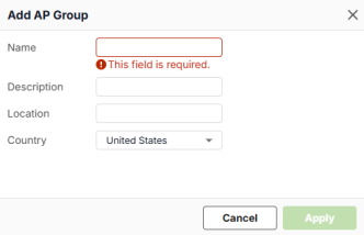 • Name: Specify the name of the AP group. You can use up to 32 characters, starting with a letter, a hyphen [-], or an underscore [_]. The valid characters are [0-9][a-z][A-Z][_-]. Spaces are not allowed. • Description: Enter a description for the group. You can use up to 61 characters. The valid characters are [A– Z], [a–z], [0–9], ['"()+,/:=?;!*#@$_%-]. Spaces are allowed. • Location: Specify the name of the place where the AP group is located. You can use up to 30 characters. The valid characters are [A– Z], [a–z], [0–9], ['()+,/:=?;!*#@$_%-]. Spaces are allowed. • Country: Select the country where the AP group is located from drop-down list. |
Advanced Mode | Select Off to disable Advanced mode. This allows you to create SSID profiles by only specifying an SSID name and optional password. |
# | This is the SSID’s index number in this list. |
Enabled | Click to turn on or off this profile. |
Name | This shows the SSID name for this profile. Click the text box and enter a new SSID if you want to change it. Enable UTF-8 SSID in Advanced Mode if you want to use special characters. |
WLAN Security | Select the encryption and authentication method used in this profile. • Select Open to allow any client to associate this network without any data encryption or authentication. This is not recommended. • Select Password and enter a pre-shared key from 8 to 63 case-sensitive keyboard characters to enable WPA1/2/3-PSK data encryption. |
The SSID Advanced Settings Screen
Use this screen to view the 2.4G/5G/6G band mode, VLAN ID, and download/upload limits. Click Wireless > WLAN Settings > SSID Settings, and enable Advanced Mode to open this screen.
The following table describes the labels in this screen.
label | description |
|---|---|
# | This is the SSID’s index number in this list. |
Enabled | Click to turn on or off this profile. |
Name | The shows the SSID name for this profile. This is the name visible on the network to wireless clients. |
WLAN Security | This shows the encryption method used in this profile. |
Band Mode | This shows the wireless band which this wireless network uses. 2.4 GHz is the frequency used by IEEE 802.11b/g/n/ax wireless clients. 5 GHz is the frequency used by IEEE 802.11ax/ac/a/n wireless clients. 6 GHz is the frequency used by IEEE 802.11ax/ac/a/n wireless clients. |
VLAN ID | This shows the VLAN ID for the AP to use to tag traffic originating from this SSID. |
Download Limit | This shows the maximum downstream bandwidth (1 to 160 Mbps) for all client traffic that will be shared. |
Upload Limit | This shows the maximum upstream bandwidth (1 to 160 Mbps) for all client traffic that will be shared. |
Tag | This shows the AP tags associated with this WiFi network (SSID). |
Setting | Click the icon to edit the SSID settings. |
Edit SSID Advanced Settings
Click Wireless > WLAN Settings > SSID Settings, enable Advanced Mode, and click Edit to open this screen.
The following table describes the labels in this screen.
label | description |
|---|---|
Enabled | Click this to enable the SSID to be discoverable by WiFi clients. |
UTF-8 SSID | Enable this to allow SSIDs to be UTF-8 encoded, allowing for more descriptive and user-friendly SSID names that could include special characters, accents, emojis and characters from different languages such as Chinese. However, be aware that some older hardware or software might not properly handle certain Unicode characters. |
Name | This shows the SSID name as it appears to WiFi clients. Click the text box and enter a new SSID if you want to change it. If you enabled UTF-8 SSID, you may enter special characters. |
Tag | Select one or more AP tags to associate with the WiFi network (SSID). Click the drop-down list to display the tags you have created for the AP group that this profile belongs to (in The AP List Screen). |
Security Options | |
Open | Select this to allow any client to associate this network without any data encryption or authentication. |
Enhanced-open | Select this to allow any client to associate this network without any password but with improved data encryption. |
WPA Personal with WPA1/WPA2/WPA3 | Select this and enter a pre-shared key from 8 to 63 case-sensitive keyboard characters to enable WPA1/2/3-PSK data encryption. Upon selecting WPA Personal With WPA3, APs that do not support it will revert to WPA2. |
MAC-based Authentication with | Select this to authenticate WiFi clients by their MAC addresses together with a user name and password. • Select External Authentication Server to use an external RADIUS server for 802.1X authentication. • Select Internal Authentication Server to use the Zyxel Device for 802.1X authentication. |
WPA-Enterprise with WPA2/WPA3 | Select this to enable 802.1X secure authentication. • Select External Authentication Server to use an external RADIUS server for 802.1X authentication. • Select Internal Authentication Server to use the Zyxel Device for 802.1X authentication. |
Band Mode | Select the WiFi band which this profile should use. 2.4 GHz is the frequency used by IEEE 802.11b/g/n/ax WiFi clients. 5 GHz is the frequency used by IEEE 802.11a/n/ac/ax WiFi clients. 6 GHz is the frequency used by IEEE 802.11ax WiFi clients. |
VLAN ID | Enter a VLAN ID for the AP to use to tag traffic originating from this SSID. |
Download Limit | Set the maximum downstream bandwidth (1 to 1000 Mbps) for all client traffic that will be shared. |
Upload Limit | Set the maximum upstream bandwidth (1 to 1000 Mbps) for all client traffic that will be shared. |
MAC-Filter Action | Use this field to allow or block clients from connecting to this SSID. Refer to The WLAN Clients Screen to configure the access policy for specific clients. • Allow: Only clients with the policy rule ‘Allow’ can connect to this SSID. All others are blocked. • Block: Only clients with the policy rule ‘Block’ cannot connect to this SSID. All others are allowed. • Disable: Any client can connect to this SSID. |
Layer 2 Isolation | This field is not configurable if you select NAT mode. Select to turn on or off layer-2 isolation. If a device’s MAC addresses is NOT listed, it is blocked from communicating with other devices in an SSID on which layer-2 isolation is enabled. Click Add to enter the MAC address of each device that you want to allow to be accessed by other devices in the SSID on which layer-2 isolation is enabled. |
Intra-BSS Traffic Blocking | Enable to prevent crossover traffic from within the same SSID. Disable to allow intra-BSS traffic. |
Band Select | Select to enable band steering. When enabled, the AP steers WiFi clients to the 5 GHz band. |
ARP Proxy | The Address Resolution Protocol (ARP) is a protocol for mapping an IP address to a MAC address. An ARP broadcast is sent to all devices on the same Ethernet network to request the MAC address of a target IP address. Select this option to allow the Zyxel Device to answer ARP requests for an IP address on behalf of a client associated with this SSID. This can reduce broadcast traffic and improve network performance. |
Assisted Roaming | Select this option to enable IEEE 802.11k/v assisted roaming on the Zyxel Device. When the connected clients request 802.11k neighbor lists, the Zyxel Device will response with a list of neighbor APs that can be candidates for roaming. |
802.11r | Select to turn on or off IEEE 802.11r fast roaming on the AP. 802.11r fast roaming reduces the delay when the clients switch from one AP to another, by allowing security keys to be stored on all APs in a network. Information from the original association is passed to the new AP when the client roams. The client does not need to perform the whole 802.1x authentication process. |
U-APSD | Select this option to enable Unscheduled Automatic Power Save Delivery (U-APSD), which is also known as WMM-Power Save. This helps increase battery life for battery-powered WiFi clients connected to the Zyxel Device using this SSID profile. |
Hidden SSID | Select this to hide the SSID from clients’ WiFi network lists. Clients will need to manually enter the SSID name to connect. |
Cancel | Click Cancel to return the screen to its last-saved settings. |
Update | Click Update to save your changes back to the Zyxel Device. |
The Radio Settings Screen
Use this screen to configure global radio settings for all managed APs.
The following table describes the labels in this screen.
label | description |
|---|---|
AP Group | Select the AP group to which the AP you want to configure belongs. Or click Add to create an AP group. |
Country | Select the country where the AP is located or installed. The available channels vary depending on the country you select. Be sure to select the correct or same country for both radios on an AP and all connected APs in order to prevent roaming failure and interference with other systems. |
Deployment Selection | • Select High-density (More than 10 APs) for the lowest output power to reduce interference to the minimum in areas where you have 10 or more Access Points. • Select Moderate-density (6-9 APs) for moderate output power to reduce interference in areas where you have 5 to 9 Access Points. • Select Low-density (2-5 APs) for higher concentration of output power for less than 5 Access Points. • Select Single AP to maximize WiFi coverage in areas where you have just 1 Access Point. |
Maximum Output Power | Selecting any of the options in the Deployment selection field will automatically set the maximum output power for 2.4/5/6 GHz. You can change the setting (1-30 dBm according to the number of APs you have in your environment. The higher the AP output power, the greater the WiFi coverage, but the more interference there will be with nearby APs). |
Channel Width | Select the wireless channel bandwidth you want the access point to use. • A standard 20 MHz channel offers transfer speeds of up to 144 Mbps (2.4 GHz) or 217 Mbps (5 GHz) whereas a 40 MHz channel uses two standard channels and offers speeds of up to 300 Mbps (2.4 GHz) or 450 Mbps (5 GHz). An IEEE 802.11ac-specific 80 MHz channel offers speeds of up to 1.3 Gbps. An IEEE 802.11be-specific 160 MHz channel offers speeds of up to 2.9 Gbps (6 GHz with 2 spatial streams) whereas a 320 MHz channel offers speeds of up to 5.8 Gbps (6 GHz with 2 spatial streams). • 40 MHz (channel bonding or dual channel) bonds two adjacent radio channels to increase throughput. An 80 MHz channel consists of two adjacent 40 MHz channels. The WiFi clients must also support 40 MHz or 80 MHz. It is often better to use the 20 MHz setting in a location where the environment hinders the WiFi signal. |
DCS Setting | |
DCS Time Interval | Enable to set the DCS (Dynamic Channel Selection) time interval (in minutes) to regulate how often an AP surveys other APs within its broadcast radius. If the channel on which it is currently broadcasting suddenly comes into use by another AP, the AP will then dynamically select the next available channel with lower interference. |
DCS Schedule | Enable to have the AP automatically find a less-used channel within its broadcast radius at a specific time on selected days of the week. You then need to select each day of the week and specify the time of the day (in 24-hour format) to have the AP use DCS to automatically scan and find a less-used channel. |
DCS Client Aware | Enable to have the AP wait until all connected clients have disconnected or currently have no traffic before switching channels. |
Avoid 5G DFS Channel | If your APs are operating in an area known to have RADAR devices, enable this to have the selected APs choose non-DFS channels to provide a stable WiFi service. |
Blacklist DFS Channels in the Presence of Radar | Enable to have the selected APs avoid DFS channels if RADAR is detected until the APs are rebooted. However, the AP can still use other non-specified DFS channels. |
2.4 GHz Channel Deployment | These settings apply to the 2.4G radio. • Select Three-Channel Deployment to limit channel switching to channels 1, 6, and 11, the three channels that are sufficiently separated to have almost no impact on one another. In other words, this allows you to minimize channel interference by limiting channel-hopping to these three “safe” channels. • Select Four-Channel Deployment to limit channel switching to four channels. If the only allowable channels in your country are 1 – 11 then the AP uses channels 1, 4, 7, 11; otherwise, the AP uses channels 1, 5, 9, 13. Four channel deployment expands your pool of possible channels while keeping the channel interference to a minimum. • Select All available channels to allow channel-hopping across all channels to have the AP automatically select the best channel. • Select Manual to specify certain individual channels that the AP can switch between. |
5 GHz Channel Deployment | These settings apply to the 5G radio. • Select All available channels to have the AP automatically select the best channel. • Select Manual to specify certain individual channels that the AP can switch between. |
6 GHz Channel Deployment | These settings apply to the 6G radio. • Select All available channels to have the AP automatically select the best channel. • Select Manual to select the individual channels the AP switches between. |
Allow Legacy Stations | Enable to have the AP allow only IEEE 802.11n/ac/ax clients to connect, and reject IEEE 802.11a/b/g clients. |
Smart Steering | Click the switch to the right to enable smart client steering on the AP. Client steering helps monitor WiFi clients and drop the connections of clients that are idle or have a low signal in order to optimize the bandwidth available for other clients. Dropped WiFi clients have may connect to an AP with a stronger signal. Additionally, dual band WiFi clients can also steer from one band to change from a busy band with many WiFi clients to a less busy band with fewer clients. Click the switch to the left to disable this feature on the AP. |
Advanced Settings | Click this to display a greater number of configuration fields. |
2.4G/5G/6G Settings | |
Disassociate Station Threshold | Set a minimum disconnect signal strength. When a WiFi client’s signal strength is lower than the specified threshold, the AP disconnects the WiFi client. –20 dBm is the strongest signal you can require for automatic disconnection and –105 dBm is the weakest. |
Optimization Aggressiveness | High, Standard and Low stand for different traffic rate threshold levels. The level you select here decides when the AP takes action to improve the access point’s WiFi network performance. The AP will postpone the actions implemented on access points until the threshold you set here is exceeded. Select a suitable traffic rate threshold level for your network. • Low: Select this if you want the AP to postpone the action while the access point network traffic is low. Select this if the AP is usually connected to only a few devices and there are no heavy users. • Standard/High: Select this if you want the AP to postpone the action only when the access point network traffic is medium to heavy. Select this if multiple users are connected at the same time and are streaming videos, using cloud services, or transferring large files. |
802.11d | Click this to enable 802.11d on the access point. 802.11d allows clients to automatically configure themselves to their local regulatory domain, ensuring compliance with country-specific rules regarding allowed frequencies, power levels, and signal bandwidth. Enabling 802.11d causes the AP to broadcast the country where it is located, which is determined by the Country setting. |
WLAN Rate Control Setting (Mbps) | Sets the minimum data rate in Mbps that 2.4 GHz, 5 GHz, and 6 GHz WiFi clients can connect to the AP. Increasing the minimum data rate can reduce network overhead and improve WiFi network performance in high density environments. However, WiFi clients that do not support the minimum data rate will not be able to connect to the AP. |
2.4GHz | Click this to display the connected APs using the 2.4 GHz frequency band. |
5GHz | Click this to display the connected APs using the 5 GHz frequency band. |
6GHz | Click this to display the connected APs using the 6 GHz frequency band. |
BandFlex | Click this to display the connected APs that supports BandFlex (5 GHz or 6 GHz frequency bands). |
Edit | Select an AP and click Edit to open a screen where you can modify the AP’s settings. |
Access Point | This displays the descriptive name or MAC address of the AP. |
Radio MAC | An AP has multiple radios, each radio typically has its own MAC address. This displays the unique MAC address of the radio inside the AP. |
Model | This displays the model name of the AP. |
Radio Mode | This displays the type of WiFi radio the AP is currently using, for example 802.11b/g/n / 802.11be. |
Channel | This displays the channel ID currently being used by the AP’s radio. |
Channel Width | This displays the wireless channel bandwidth the AP’s radio is set to use. |
Transmit Power | This displays the current transmitting power of the AP’s radio. If the AP is offline, this shows the maximum output power you configured for the AP. |
Smart Steering | This displays whether smart client steering is enabled or disabled on the connected APs. |
Antenna | This displays the antenna orientation settings for the AP that comes with internal antennas and also has an antenna switch. |
Airtime Fairness | This displays whether airtime fairness is enabled or disabled on the AP. With enabled Airtime Fairness, the AP allocates airtime equally between all connected clients. See Airtime Fairness for the details. |
The Wireless > WLAN Settings > Radio Settings > Edit Band Screen
For some radio settings, you can configure them either on an AP group or on individual APs. By default, an AP uses the settings of the AP group it belongs to. Use this screen to configure the radio settings on each individual AP. The settings on each individual AP takes the priority over the group setting.
Go to Wireless > WLAN Settings > Radio Settings, then click the edit icon of the AP you want to configure.
The following table describes the labels in this screen.
label | description |
|---|---|
Access Points | This displays the descriptive name or MAC address of the AP. |
Radio MAC | An AP has multiple radios, each radio typically has its own MAC address. This displays the unique MAC address of the wireless radio interface inside the AP. |
AP Model | This displays the model name of the AP. |
Band | This displays the frequency band the AP is currently using. When configuring an AP with BandFlex, select a frequency band to use together with the 2.4 GHz band. |
Radio Mode | Select how to let WiFi clients connect to the AP. If 802.11 Band is set to 2.4GHz: • Auto (Up to 802.11ax): allows either IEEE802.11b, IEEE802.11g, IEEE802.11n, and IEEE802.11ax compliant WiFi devices to associate with the AP. The AP adjusts the transmission rate automatically according to the WiFi standard supported by the wireless devices. • 802.11b/g: allows either IEEE 802.11b or IEEE 802.11g compliant WiFi devices to associate with the AP. • 802.11b/g/n: allows IEEE802.11b, IEEE802.11g and IEEE802.11n compliant WiFi devices to associate with the AP. • 802.11ax: allows IEEE802.11b, IEEE802.11g, IEEE802.11n, and IEEE802.11ax compliant WiFi devices to associate with the AP. If the WiFi device isn’t compatible with 802.11ax, the AP will communicate with the WiFi device using 802.11n, and so on. • 802.11be: allows IEEE802.11b, IEEE802.11g, IEEE802.11n, IEEE802.11ax and IEEE802.11be compliant WiFi devices to associate with the AP. If the WiFi device isn’t compatible with 802.11be, the AP will communicate with the WiFi device using 802.11ax, and so on. If 802.11 Band is set to 5GHz: • Auto: allows either IEEE802.11a, IEEE802.11n, IEEE802.11ac, IEEE802.11ax, and IEEE802.11be compliant WiFi devices to associate with the AP. The AP adjusts the transmission rate automatically according to the WiFi standard supported by the wireless devices. • 802.11a: allows only IEEE 802.11a compliant WiFi devices to associate with the AP. • 802.11a/n: allows both IEEE802.11n and IEEE802.11a compliant WiFi devices to associate with the AP. • 802.11ac: allows IEEE802.11n, IEEE802.11a, and IEEE802.11ac compliant WiFi devices to associate with the AP. If the WiFi device isn’t compatible with 802.11ac, the AP will communicate with the WiFi device using 802.11n, and so on. • 802.11ax: allows IEEE802.11n, IEEE802.11a, IEEE802.11ac, and IEEE802.11ax compliant WiFi devices to associate with the AP. If the WiFi device isn’t compatible with 802.11ax, the AP will communicate with the WiFi device using 802.11ac, and so on. • 802.11be: allows IEEE802.11a, IEEE802.11n, IEEE802.11ac, IEEE802.11ax and IEEE802.11be compliant WiFi devices to associate with the AP. If the WiFi device isn’t compatible with 802.11be, the AP will communicate with the WiFi device using 802.11ax, and so on. If 802.11 Band is set to 6GHz: • Auto: allows either IEEE802.11ax and IEEE802.11be compliant WiFi devices to associate with the AP. The AP adjusts the transmission rate automatically according to the WiFi standard supported by the wireless devices. • 802.11ax: allows IEEE802.11ax compliant WiFi devices to associate with the AP. • 802.11be: allows IEEE802.11be compliant WiFi devices to associate with the AP. If the WiFi device isn’t compatible with 802.11be, the AP will communicate with the WiFi device using 802.11ax. |
Channel | |
Channel Width | Select the wireless channel bandwidth you want the AP to use. A standard 20 MHz channel offers transfer speeds of up to 144 Mbps (2.4 GHz) or 217 Mbps (5 GHz) whereas a 40 MHz channel uses two standard channels and offers speeds of up to 300 Mbps (2.4 GHz) or 450 Mbps (5 GHz). An IEEE 802.11ac-specific 80 MHz channel offers speeds of up to 1.3 Gbps. An IEEE 802.11be-specific 160 MHz channel offers speeds of up to 2.9 Gbps (6 GHz with 2 spatial streams) whereas a 320 MHz channel offers speeds of up to 5.8 Gbps (6 GHz with 2 spatial streams). 40 MHz (channel bonding or dual channel) bonds two adjacent radio channels to increase throughput. An 80 MHz channel consists of two adjacent 40 MHz channels. The WiFi clients must also support 40 MHz or 80 MHz. It is often better to use the 20 MHz setting in a location where the environment hinders the WiFi signal.Select 20MHz if you want to lessen radio interference with other wireless devices. • Select Group Setting to use the channel bandwidth configured for the AP group this AP belongs to. • Select 40MHz to allow the AP to choose the channel bandwidth (20 or 40 MHz) that has least interference. • Select 80MHz to allow the AP to choose the channel bandwidth (20, 40 or 80) that has least interference. • Select 160MHz to allow the AP to choose the channel bandwidth (20, 40, 80 or 160MHz) that has least interference. • Select 240MHz to allow the AP to choose the channel bandwidth (20, 40, 80, 160 or 240MHz) that has least interference. • Select 320MHz to allow the AP to choose the channel bandwidth (20, 40, 80, 160, 240 or 320 MHz) that has least interference. |
Maximum Output Power | • Select Group Setting to use the maximum output power configured for the AP group this AP belongs to. • If there is a high density of APs in an area, decrease the output power of the AP to reduce interference with other APs. You can change the setting from 1 to 30 dBm. |
Airtime Fairness | Click the switch to the right to enable Airtime Fairness to have the AP allocate airtime equally between all connected clients. Airtime fairness makes sure clients that can receive packets faster will not be slowed down by clients that receive packets slower. Use this if clients that need less airtime in your wireless networks need priority to receive packets, such as clients that use real time traffic to stream videos or play games. This field is not available if the AP does not support airtime fairness. Note that if you enable this feature, clients that originally need more time to receive packets will become slower than before. Clear the check box if you want better performance on slower clients in your network, such as a gaming computer that’s far away from the AP. |
Antenna Setting | This allows you to adjust coverage depending on the antenna orientation of the AP’s radios for better coverage. This field is not available if the AP does not allow you to adjust antenna orientation. Select Wall if you mount the AP to a wall. Select Ceiling if the AP is mounted on a ceiling. You can switch from Wall to Ceiling if there are still wireless dead zones, and vice versa. |
Smart Steering | • Select Group Setting to use the radio setting you configured for the AP group this AP belongs to. • Select Custom to configure a different radio setting from the group setting. |
Enabled | Click the switch to the right to enable smart client steering on the AP. Client steering helps monitor WiFi clients and drop the connections of clients that are idle or have a low signal in order to optimize the bandwidth available for other clients. Dropped WiFi clients have may connect to an AP with a stronger signal. Additionally, dual band WiFi clients can also steer from one band to change from a busy band with many WiFi clients to a less busy band with fewer clients. Click the switch to the left to disable this feature on the AP. |
Disassociate Station Threshold | Set a minimum disconnect signal strength. When a WiFi client’s signal strength is lower than the specified threshold, the AP disconnects the WiFi client. –20 dBm is the strongest signal you can require for automatic disconnection and –105 dBm is the weakest. |
Optimization Aggressiveness | High, Standard and Low stand for different traffic rate threshold levels. The level you select here decides when the AP takes action to improve the access point’s WiFi network performance. The AP will postpone the actions implemented on access points until the threshold you set here is exceeded. Select a suitable traffic rate threshold level for your network. • Low: Select this if you want the AP to postpone the action while the access point network traffic is low. Select this if the AP is usually connected to only a few devices and there are no heavy users. • Standard/High: Select this if you want the AP to postpone the action only when the access point network traffic is medium to heavy. Select this if multiple users are connected at the same time and are streaming videos, using cloud services, or transferring large files. |
Cancel | Click Cancel to return the screen to its last-saved settings. |
Update | Click Update to save your changes back to the Zyxel Device. |
The AP Settings Screen
Use this screen to configure general AP settings and enable or disable a port on the managed AP and configure the port’s VLAN settings. The port settings apply to all managed APs in the selected group and have one or more than one Ethernet LAN port (except the uplink port).
The following table describes the labels in this screen.
label | description |
|---|---|
AP Group | Select the AP group to which the AP you want to configure belongs. Or click Add to create an AP group. |
General Setting | |
Smart Mesh | Click to enable or disable the Smart Mesh feature on all managed APs in the selected group. Smart Mesh is a WiFi mesh solution for APs. With Smart Mesh, you can have two or more APs automatically create a mesh network within your home or office, ensuring there are no areas with a weak WiFi signal. |
Ethernet Failover | When enabled, a wired AP connected to the Zyxel Device changes its role from mesh controller to mesh extender if the AP is unable to reach the Zyxel Device. When disabled, a wired AP connected to the Zyxel Device automatically changes its role from mesh controller to mesh extender only if the AP’s uplink Ethernet cable is unplugged. |
Load Balancing Setting AP load balancing lets the Zyxel Device distribute WiFi clients and traffic across APs connected to the Zyxel Device to prevent overloading of APs with higher loads and lower signal quality. | |
Mode | With load balancing enabled, when an AP reaches the set limit, new clients are steered to another AP in the group. Select a mode for this AP group to distribute client devices evenly across multiple access points. |
Disabled | Select this to disable load balancing on all the APs in this AP group. |
By Client Device Number Mode | Select this to balance network traffic based on the number of client devices connected to an AP. |
2.4G / 5G / 6G Maximum client device number | Enter the maximum number of client devices (1 to 127) that can simultaneously use a radio band. |
Disassociate client device when overloaded | Turn this on to disconnect clients to the APs when they become overloaded. Turn this off to disable this option. The APs will then either delay the connection until they have enough bandwidth or transfer the connection to other APs within its broadcast range. The disassociation priority is determined automatically by the Zyxel Device and is as follows: • Idle Time – Client devices that have been idle the longest will be disconnected first. If none of the connected devices are idle, then the priority shifts to Signal Strength. • Signal Strength – Client devices with the weakest signal strength will be disconnected first. |
Smart Classroom Mode | Select this to balance network traffic based on the number of client devices connected in an e-learning environment. APs ignore association requests and authentication request packets from any new client device when the maximum number of client devices is reached. |
2.4G / 5G / 6G Maximum client device number | Enter the maximum number of client devices (1 to 127) at which an AP begins load balancing its connections. |
Group Port Settings | |
LAN x | This is the name of the physical Ethernet port on the AP. This section lets you configure global port VLAN settings for all managed APs. |
PVID | Enter the port’s PVID. A PVID (Port VLAN ID) is a tag that adds to incoming untagged frames received on a port so that the frames are forwarded to the VLAN group that the tag defines. |
Allowed VLANs | Enter the VLAN ID numbers to which the port belongs. Only the network traffic from the allowed VLANs will be sent or received through this port. You can enter individual VLAN ID numbers separated by a comma or a range of VLANs by using a dash, such as 1, 3, 5–8. |
Reset | Click Reset to return the screen to its last-saved settings. |
Apply | Click Apply to save your changes back to the Zyxel Device. |
Custom Port Settings | This displays the individual settings of the APs in the selected AP group. |
Access Points | This displays the descriptive name or MAC address of the AP. |
Overwrite Settings | • This displays Enable if the individual settings on the AP differ from the Group Port Settings. • This displays Disable if the individual settings on the AP are the same as the Group Port Settings. This field is blank if the AP does not have LAN ports. |
Port Status | • If the AP has LAN ports, this displays whether the port settings on each AP’s LAN ports are enabled or not. • If the AP does not have LAN ports, this displays whether the AP’s wireless bridge is enabled or not. |
Port Setting | This displays the details of the AP’s PVID and allowed VLANs settings. |
Setting | Click the icon to edit the AP’s port settings. |
The Wireless > WLAN Settings > AP Settings > Edit AP Screen
By default, an AP uses the port settings of the AP group it belongs to. Use this screen to configure the port settings on each individual AP. The settings on each individual AP takes the priority over the group setting.
Go to Wireless > WLAN Settings > AP Settings, then click the edit icon of the AP you want to configure from the Custom Port Settings.
The following table describes the labels in this screen.
label | description |
|---|---|
Access Points | This displays the descriptive name or MAC address of the AP. |
Overwrite Settings | Click the switch to the right to make the AP use its individual settings instead of the Group Port Settings. |
LAN x | This is the name of the physical Ethernet port on the AP. Click the switch to the right to enable the configured port setting for the port. |
PVID | Enter the port’s PVID. A PVID (Port VLAN ID) is a tag that adds to incoming untagged frames received on a port so that the frames are forwarded to the VLAN group that the tag defines. |
Allowed VLANs | Enter the VLAN ID numbers to which the port belongs. Only the network traffic from the allowed VLANs will be sent or received through this port. You can enter individual VLAN ID numbers separated by a comma or a range of VLANs by using a dash, such as 1, 3, 5–8. |
Wireless Bridge | Wireless bridge enables two devices to automatically bridge two network segments through a WiFi connection. When enabled, the system automatically creates VLAN and bridge interfaces according to the Allowed VLANs you configure. |
Allowed VLANs | Enter the VLAN ID numbers that the Zyxel Device will forward over the wireless bridge. The traffic with entered VLAN IDs can pass through the wireless bridge. You can enter individual VLAN ID numbers separated by a comma or a range of VLANs by using a dash, such as 1, 3, 5–8. |
Cancel | Click Cancel to return the screen to its last-saved settings. |
Apply | Click Apply to save your changes back to the Zyxel Device. |
The AP Group Settings Screen
Use this screen to configure AP group settings and remove an AP group.
The following table describes the labels in this screen.
label | description |
|---|---|
AP Group | Select the AP group to which the AP you want to configure belongs. Or click Add to create an AP group. |
Name | This displays the AP group to which the AP you want to configure belongs. |
Description | Enter a description for this group. You can use up to 31 characters, spaces and underscores allowed. |
Location | Specify the name of the place where the AP group is located. |
Remove Group | Select an entry and click this button to remove it from the AP group list. |
Reset | Click Reset to return the screen to its last-saved settings. |
Apply | Click Apply to save your changes back to the Zyxel Device. |
The Wireless Health Screen
Use this screen to monitor the health of WiFi networks for your APs and connected WiFi clients.
The following table describes the labels in this screen.
label | description |
|---|---|
Auto Optimization | |
2.4 GHz Radio | Select this to have the AP scan and choose a radio channel that has least interference. |
5 GHz Radio | Select this to have the AP change the channel bandwidth from 80 MHz to 20 MHz to reduce the radio interference with other APs. If the AP wireless performance has not improved, the Zyxel Device will have the AP scan and choose a radio channel that has least interference. |
6 GHz Radio | Select this to have the AP change the channel bandwidth to reduce the radio interference with other APs. • For WiFi 7 APs, the channel bandwidth changes from 320 MHz to 80 MHz. • For WiFi 6E APs, the channel bandwidth changes from 160 MHz to 80 MHz. If the AP wireless performance has not improved, the Zyxel Device will have the AP scan and choose a radio channel that has least interference. |
Client | Select this to have the AP try to steer the wireless clients in poor health to an AP or SSID with a strong signal every 30 minutes. |
Optimization Aggressiveness | High, Standard and Low stand for different traffic rate threshold levels. The level you select here decides when the Zyxel Device takes actions to improve the APs wireless network performance. The Zyxel Device will postpone the actions implemented on APs until your network is less busy if the threshold is exceeded. Select a suitable traffic rate threshold level for your network. • High: Select this if you want the Zyxel Device to postpone the action set when the AP network traffic is heavy. • Standard: Select this if you want the Zyxel Device to postpone the action set when the AP network traffic is medium. • Low: Select this if you want the Zyxel Device to postpone the action set when the AP network traffic is low. |
Cancel | Click Cancel to return the screen to its last-saved settings. |
Apply | Click Apply to save your changes back to the Zyxel Device. |