AP Diagnostics
Overview
Use the AP diagnostics screens for troubleshooting.
What You Can Do in this Chapter
• Use the Diagnostics screen (see Diagnostics Screen) to generate a file containing the managed APs’ diagnostic information.
• Use the Packet Capture screen (see Packet Capture Screen) to generate a file containing specific network traffic passing through the managed APs for troubleshooting wireless connection issues.
• Use the Remote Capture screen (see Remote Capture Screen) to enable remote packet captures on wired or wireless interfaces through an external packet analyzer.
Diagnostics Screen
Use this screen to generate a file containing the managed AP’s diagnostic information.
The following table describes the labels in this screen.
Label | Description |
|---|---|
Diagnostics Collect | |
AP | Select the managed AP(s) whose diagnostic information you want to collect. You can select up to five APs. Diagnostic data from each AP is stored in an individual AP diagnostic file. |
Storage | Select Onboard to store diagnostic information on the Zyxel Device. Select USB to store diagnostic information on a USB storage device connected to the Zyxel Device if the Zyxel Device allows this. |
Action | Start collect info: Click this to start collecting diagnostic information. Stop collect info: Click this to stop collecting diagnostic information. A file will not be created. |
Status | This shows Standby when no collection is in progress and Collecting during data collection. |
APs Process | This shows the number of APs selected for collection and the number of APs that have completed the collection. For example, 2/3 means that three APs are being collected and two of them have finished. If the status shows Standby while one or more APs have not finished data collection, check the details in Log & Report > Log / Events > System under the System category. After resolving the issue, click Start Collect Info in the Action field to restart the collection. |
Diagnostic Files | |
Onboard / USB | Select the tab to view the diagnostic files saved on the Zyxel Device or a connected USB storage device. |
Remove | Select files and click Remove to delete them from the Zyxel Device or the USB storage device. |
Download | Select a diagnostic file and click Download to save it to your computer. |
File Name | This is the name of the created diagnostic file. An AP diagnostic file name starts with “apdiaginfo”, followed by the AP’s MAC address. |
Size | This is the size (in bytes) of the created diagnostic file. |
Modified Time | This is the date and time that the diagnostic file was created. The format is mm dd hh:mm. |
Packet Capture Screen
Use this screen to capture specific traffic of the managed APs’ WiFi network for troubleshooting. You can then download the capture files for analysis.
The following table describes the labels in this screen.
Label | Description |
|---|---|
Packets to Capture | |
AP Group | Select the AP group the managed APs whose packets you want to capture belongs to. |
AP | Select the managed APs whose packets you want to capture. |
Interface | Select the interfaces for which to capture packets passing through the managed APs. If multiple interfaces are selected and the field is too short, extra interfaces are shown as +<number>. • SSID Name (xGHz): WiFi packets on a specific WiFi network (SSID) or a specific frequency band. x indicates the frequency band. • WIRELESS (xGHz): WiFi packets transmitted and received by client devices on a specific frequency band. x indicates the frequency band. • WDS-x-9: WiFi packets transmit through the downlink AP using a specific radio profile. x indicates the radio profile number 1, 2, or 3. • WDS-x-10: WiFi packets transmit through the uplink AP using a specific radio profile. x indicates the radio profile number 1, 2, or 3. • UPLINK: Packets transmitted and received through the uplink port. • LANx: Packets passing through a specific LAN port of the managed AP. x indicates the LAN port number. • Br0: Packets transmitted and received through the AP's virtual bridge, connecting uplink and downlink interfaces. Learn more about Uplink and Downlink. |
Storage | This displays Onboard if the capture file is saved on the Zyxel Device, and USB if the capture file is saved to a connected USB storage device. Click the Edit icon in the Action field to change this setting. |
Action | Refresh: Click this to update the packet captures on the interfaces you selected above. Edit: Click this to configure additional details, such as setting a filter to capture specific packets. Start packet capturing: Click this to start capturing packets from the selected interfaces you selected above. If packet capture fails because of insufficient storage, you can download the existing files to your computer and remove them from the Zyxel Device or USB storage. Stop packet capturing: Click this to stop capturing packets. The captured packets will be saved to a capture file. You can find the files below on the screen. |
Status | The status displays Idle when no packet capture is in progress, Preparing while the AP retrieves capture requirements, and Capturing when packet capture is active. |
Capture Packets | |
Onboard / USB | Select the tab to view the capture packet files saved on the Zyxel Device or a connected USB storage device. |
Remove | Select files and click Remove to delete them from the Zyxel Device or the USB storage device. |
Download | Select a file and click Download to save it to your computer. |
File Name | This is the name of the created packet capture file. |
Size | This is the size (in bytes) of the created packet capture file. |
Modified Time | This is the date and time that the packet capture file was created. The format is mm dd hh:mm. |
Packet Capture Edit Screen
Use this screen to configure additional details for packets capture network traffic.
The following table describes the labels in this screen.
Label | Description |
|---|---|
Filter | |
IP Version | Select the packets with a specific IP version that you want to capture. Select any to capture packets for all IP versions. |
Protocol Type | Select the packets with a specific protocol type that you want to capture. Give an example of a protocol. Select any to capture packets for all types of traffic. |
Host IP | Enter the packets from a specific IP host that you want to capture. Enter any to capture packets for all hosts. |
Host Port | This field is configurable when you set the Protocol Type to any, tcp, or udp. Enter the port number for the Protocol Type to selected above. For example, FTP traffic is port 21 for Protocol Type TCP. |
Misc setting | |
Per AP File Size | Specify a maximum size limit in megabytes (MB) for the total combined size of all the capture files from each AP. The valid range is 1 to 10 MB. The Zyxel Device stops capturing when the size limit is reached. |
Duration | Set a time limit in seconds for the capture. The Zyxel Device stops the capture and generates the capture file when either this period of time has passed or the file reaches the size specified in the Per AP File Size field. 0 means there is no time limit. |
File Suffix | Specify text to add to the end of the file name (before the dot and filename extension) to help you identify the packet capture files. Modifying the file suffix also avoids making new capture files that overwrite existing files of the same name. The file name format is “interface name-file suffix.cap”, for example “vlan2-packet-capture.cap”. |
Bytes To Capture | Specify the maximum number of bytes to capture per packet. The Zyxel Device automatically truncates packets that exceed this size. As a result, when you view the packet capture files in a packet analyzer, the actual size of the packets may be larger than the size of captured packets. |
Storage | Select Onboard to have the Zyxel Device stores packet capture files on the Zyxel Device. Select USB to have the Zyxel Device stores packet capture files on a USB storage device connected to the Zyxel Device if the Zyxel Device allows this. |
Apply | Click this button to save your changes. |
Cancel | Click this button to return the screen to its last-saved settings. |
Remote Capture Screen
Use this screen to capture wireless traffic going through a managed AP and output the captured packets to a packet analyzer (also known as network or protocol analyzer) such as Wireshark.
You can connect your laptop running a network analyzer to a switch, along with AP2 configured as a monitor AP, to capture wireless traffic between AP1 and its client devices (Cs).
Remote Capture 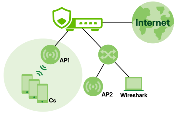
The following table describes the labels in this screen.
Label | Description |
|---|---|
General Settins | |
Select AP For Remote Capture | Select the managed AP that is connected to the device used for capturing wireless packets. This AP will act as the monitor AP. |
Query | After selecting a managed AP, click this button to see its IP address and remote capture status. |
Remote Capture Status | |
Selected AP | This is the name of the managed AP you select. |
AP IP Address | This is the IP address of the managed AP you select. |
Server Port | Enter the number of the server port you want the packet analyzer to connect to in order to capture traffic going through the managed AP. The default port number is 2002. |
Capture Status | This displays Enabled when remote capture is in progress and Disabled when no remote capture is in progress. |
Start / Stop | Click the Start button to allow the packet analyzer to start capturing traffic going through the managed AP. Click the Stop button to stop the packet analyzer from capturing traffic going through the managed AP. |