Hardware Panels
This chapter describes the front panel and rear panel of the Switch and shows you how to make the hardware connections.
Switch Hardware Features
The following table describes the hardware features of the Switch by model.
FEATURE | XMG2230-28HP | XMG2230-52HP |
|---|---|---|
Stacking Mode | Yes (future option) | Yes (future option) |
10/100/1000 Mbps PoE Ports | No | 32 |
100/1000 Mbps / 2.5 Gbps PoE Ports | 24 | 16 |
1/10 Gbps SFP+ Interface | 4 | 4 |
Total system ports | 28 | 52 |
Smart FAN | 3 | 3 |
Console Port | USB-C | USB-C |
Power Supply | AC x 1 | AC x 1 |
External DC Connector | Yes | Yes |
CPU | 1 GHz MIPS-Dual core | 1 GHz MIPS-Dual core |
Flash (MB) | 64 | 64 |
RAM (GB) | 1 | 1 |
Jumbo Frame (Bytes) | 12K | 12K |
Retainer clip for power cord | Yes | Yes |
Front Panel Connections
Front Panel: XMG2230-28HP
Front Panel: XMG2230-52HP
The following table describes the ports.
CONNECTOR | description |
|---|---|
24 2.5GBase-T RJ-45 PoE++ Ports (XMG2230-28HP) | These are 100/1G/2.5GBase-T auto-negotiating and auto-crossover IEEE802.3bt PoE++ ports. Connect these ports to a computer, a hub, a router, or an Ethernet switch. |
16 1000Base-T RJ-45 PoE+ Ports (XMG2230-52HP) | These are 10/100/1000Base-T auto-negotiating and auto-crossover IEEE802.3at PoE+ 30 W ports. Connect these ports to a PTZ (pan, tilt and zoom) camera, a WiFi 6/7 (802.11ax/802.11be) router, a WiFi 6/7 (802.11ax) AP, or an Ethernet switch. |
16 1000Base-T RJ-45 PoE++ Ports (XMG2230-52HP) | These are 10/100/1000Base-T auto-negotiating and auto-crossover IEEE802.3bt PoE++ 60 W ports. Connect these ports to a PTZ (pan, tilt and zoom) camera, a WiFi 6/7 (802.11ax/802.11be) router, a WiFi 6/7 (802.11ax) AP, or an Ethernet switch. |
16 2.5GBase-T RJ-45 PoE++ Ports (XMG2230-52HP) | These are 100/1000/2.5GBase-T auto-negotiating and auto-crossover IEEE802.3bt PoE++ 60 W ports. Connect these ports to a PTZ (pan, tilt and zoom) camera, a WiFi 6/7 (802.11ax/802.11be) router, a WiFi 6/7 (802.11ax) AP, or an Ethernet switch. |
4 1/10G SFP+ Slots | Use SFP+ transceivers in these ports for high-bandwidth backbone connections. You can also insert an SFP+ Direct Attach Copper (DAC) in the SFP+ slot. |
Reset | Press the RESET button to reboot the Switch without turning the power off. See LEDs for more information about the LED behavior. |
Restore | In Standalone Mode Press the RESTORE button for 3 to 7 seconds until the power (PWR/SYS) LED blinks rapidly yellow, allowing the Switch to reboot and restore the custom default file. See LEDs for more information about the LED behavior. Press the RESTORE button for more than 7 seconds until the power (PWR/SYS) LED blinks slowly yellow, allowing the Switch to reboot and restore the factory default file. See LEDs for more information about the LED behavior. In Nebula Cloud Mode Press the RESTORE button for more than 3 seconds to have the Switch automatically reboot and restore the factory default file. |
Multi-Gigabit Ethernet Ports
The Switch has 2.5 GbE auto-negotiating, auto-crossover Ethernet ports. In 100/1000 Mbps/2.5 Gbps multi-gigabit Ethernet, the speed can be 100 Mbps, 1000 Mbps, or 2.5 Gbps. The duplex mode is full duplex.
An auto-negotiating port can detect and adjust to the optimum Ethernet speed (100/1000 Mbps/2.5 Gbps) of the connected device in full duplex mode.
An auto-crossover (auto-MDI/MDI-X) port automatically works with a straight-through or crossover Ethernet cable.
When auto-negotiation is turned on, an Ethernet port negotiates with the peer automatically to determine the connection speed and duplex mode. If the peer Ethernet port does not support auto-negotiation or turns off this feature, the Switch determines the connection speed by detecting the signal on the cable and using half duplex mode. When the Switch’s auto-negotiation is turned off, an Ethernet port uses the pre-configured speed and duplex mode when making a connection, thereby requiring you to make sure that the settings of the peer Ethernet port are the same in order to connect.
Default Ethernet Negotiation Settings
The factory default negotiation settings for the GigabitEthernet ports on the Switch are:
• Speed: Auto
• Duplex: Auto
• Flow control: Off
• Link Aggregation: Disabled
Auto-crossover
All ports support auto-crossover, that is auto-MDIX ports (Media Dependent Interface Crossover), so you may use either a straight-through Ethernet cable or crossover Ethernet cable for all Gigabit port connections. Auto-crossover ports automatically sense whether they need to function as crossover or straight ports, so crossover cables can connect both computers and switches or hubs.
SFP/SFP+ Slots
These are four slots for Small Form-Factor Pluggable (SFP) or SFP+ modules, such as an SFP or SFP+ transceiver. The SFP+ (SFP Plus) is an enhanced version of the SFP and supports data rates of 10 Gbps. A transceiver is a single unit that houses a transmitter and a receiver. Use a transceiver to connect a fiber optic cable to the Switch. The Switch does not come with transceivers. You must use transceivers that comply with the Small Form-Factor Pluggable (SFP) Transceiver MultiSource Agreement (MSA). See the SFF committee’s INF-8074i specification Rev 1.0 for details.
You can change transceivers while the Switch is operating. You can use different transceivers to connect to Ethernet switches with different types of fiber optic connectors.
• Type: SFP or SFP+ connection interface
• Connection speed: 1 or 10 Gigabit per second (Gbps)
WARNING! To avoid possible eye injury, do not look into an operating fiber optic module’s connectors.
HANDLING! All transceivers are static sensitive. To prevent damage from electrostatic discharge (ESD), it is recommended you attach an ESD preventive wrist strap to your wrist and to a bare metal surface when you install or remove a transceiver.
STORAGE! All modules are dust sensitive. When not in use, always keep the dust plug on. Avoid getting dust and other contaminant into the optical bores, as the optics do not work correctly when obstructed with dust.
HANDLING! All transceivers are static sensitive. To prevent damage from electrostatic discharge (ESD), it is recommended you attach an ESD preventive wrist strap to your wrist and to a bare metal surface when you install or remove a transceiver.
STORAGE! All modules are dust sensitive. When not in use, always keep the dust plug on. Avoid getting dust and other contaminant into the optical bores, as the optics do not work correctly when obstructed with dust.
Transceiver Installation
Use the following steps to install a transceiver.
1 Attach an ESD preventive wrist strap to your wrist and to a bare metal surface.
2 Align the transceiver in front of the slot opening.
3 Make sure the latch is in the lock position (latch styles vary), then insert the transceiver into the slot with the exposed section of PCB board facing down.
4 Press the transceiver firmly until it clicks into place.
5 The Switch automatically detects the installed transceiver. Check the LEDs to verify that it is functioning properly.
6 Remove the dust plugs from the transceiver and cables (dust plug styles vary).
7 Identify the signal transmission direction of the fiber optic cables and the transceiver. Insert the fiber optic cable into the transceiver.
Latch in the Lock Position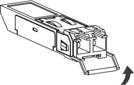
Transceiver Installation Example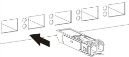
Connecting the Fiber Optic Cables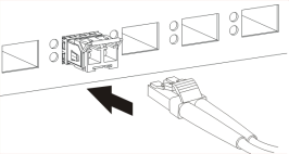
Transceiver Removal
Use the following steps to remove an SFP transceiver.
1 Attach an ESD preventive wrist strap to your wrist and to a bare metal surface on the chassis.
2 Remove the fiber optic cables from the transceiver.
3 Pull out the latch and down to unlock the transceiver (latch styles vary).
 Make sure the transceiver’s latch is pushed all the way down, so the transceiver can be pulled out successfully.
4 Pull the latch, or use your thumb and index finger to grasp the tabs on both sides of the transceiver, and carefully slide it out of the slot.
Do NOT pull the transceiver out by force. You could damage it. If the transceiver will not slide out, grasp the tabs on both sides of the transceiver with a slight up or down motion and carefully slide it out of the slot. If unsuccessful, contact Zyxel Support to prevent damage to your Switch and transceiver.5 Insert the dust plug into the ports on the transceiver and the cables.
Removing the Fiber Optic Cables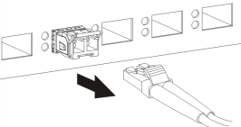
Opening the Transceiver’s Latch Example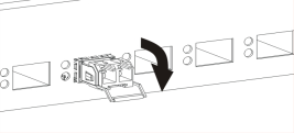
Transceiver Removal Example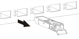
Console Port
Connect this port to your computer (using an USB Type C console cable) if you want to configure the Switch using the command line interface (CLI) through the console port.
Rear Panel
The following figures show the rear panel of the Switch. The rear panel contains:
Rear Panel: XMG2230-28HP
Rear Panel: XMG2230-52HP
Grounding
Grounding is a safety measure to direct excess electric charge to the ground. It prevents damage to the Switch, and protects you from electrocution. Use the grounding screw on the rear panel and the ground wire of the AC power supply to ground the Switch.
The grounding terminal and AC power ground where you install the Switch must follow your country’s regulations. Qualified service personnel must ensure the building’s protective earthing terminals are valid terminals.
Installation of Ethernet cables must be separate from AC power lines. To avoid electric surge and electromagnetic interference, use a different electrical conduit or raceway (tube/trough or enclosed conduit for protecting electric wiring) that is 15 cm apart, or as specified by your country’s electrical regulations.
Any device that is located outdoors and connected to this product must be properly grounded and surge protected. To the extent permissible by your country’s applicable law, failure to follow these guidelines could result in damage to your Switch which may not be covered by its warranty.
The specification for surge or ESD protection assumes that the Switch is properly grounded.1 Remove the M4 ground screw from the Switch’s rear panel.
2 Secure a green or yellow ground cable (16 AWG or smaller) to the Switch's rear panel using the M4 ground screw.
Grounding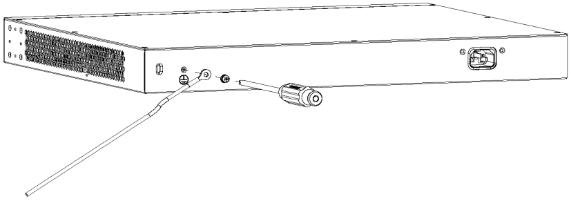
3 Attach the other end of the ground cable to a grounding bar located on the rack where you install the Switch or to an on-site grounding terminal.
Attach Ground Cable to Grounding Bar or On-site Grounding Terminal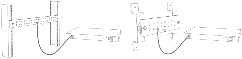
4 The grounding terminal of the server rack or on-site grounding terminal must also be grounded and connected to the building’s main grounding electrode. Make sure the grounding terminal is connected to the buildings grounding electrode and has an earth resistance of less than 10 ohms, or according to your country’s electrical regulations.
Connecting to the Building’s Main Grounding Electrode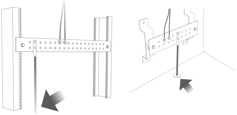
If you are uncertain that suitable grounding is available, contact the appropriate electrical inspection authority or an electrician.
This device must be grounded. Do this before you make other connections.
AC Power Connection
Make sure you are using the correct power source as shown on the panel and that no objects obstruct the airflow of the fans.To connect power to the Switch, insert the female end of the power cord to the AC power receptacle on the rear panel. Connect the other end of the supplied power cord to a power outlet.
Power Cord Requirement (XMG2230-52HP)
Make sure to use the provided or designated power cord for your Switch.
If you need to replace the power cord, contact your local vendor.DC Power Connection
The Switch uses a single D-sub series terminal block plug with 14 pins. Use 14 wires to connect to the three terminal blocks: 6 for the 6 positive terminals, 6 for the 6 negative terminals, and 2 for the ground.
The current rating of the power wires must be greater than 20 Amps. The power supply to which the Switch connects must have a built-in circuit breaker or switch to toggle the power.When installing the Switch power wire, push the wire firmly into the terminal as deep as possible and make sure that no exposed (bare) wire can be seen or touched.Exposed power wire is dangerous. Use extreme care when connecting a DC power source to the device.
WARNING! Working with high-voltage DC power is dangerous. To ensure safety of equipment and regulatory compliance, the DC power connection must be performed by a certified technician.
To connect a power supply:
1 Connect one end of the grounding wire to the terminal block’s grounding pin and insert it all the way in.
2 Connect the other end of the grounding cable to the building’s main grounding electrode. Do this for the other grounding wire.
3 Connect one end of the power wire to the terminal block’s positive pin and insert it all the way in.
4 Connect the other end of the power wire to the positive terminal on the DC power supply. Do this for the 6 positive wires.
5 Connect one end of the power wire to the terminal block’s negative pin and insert it all the way in.
6 Connect the other end of the power wire to the negative terminal on the power supply. Do this for the 6 negative wires.
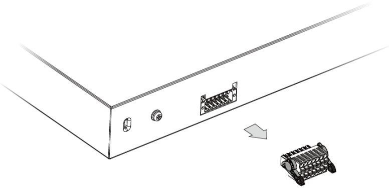
7 Push the lever upward on both sides of the terminal block (1). Then, push the terminal block fully into the Switch’s DC INPUT connector (2).
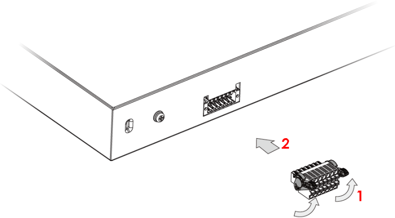
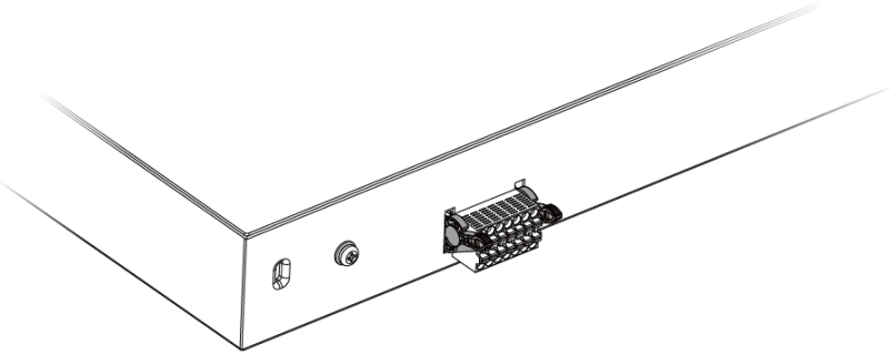
To disconnect the terminal block:
1 Push the lever downward on both sides of the terminal block.
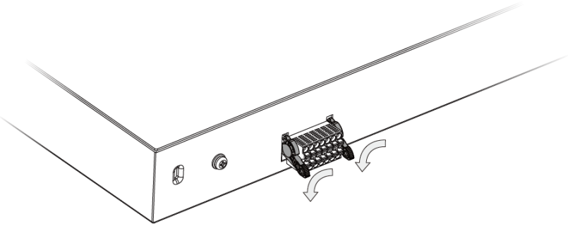
2 Pull the terminal block to detach it from the Switch’s DC INPUT connector.
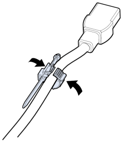
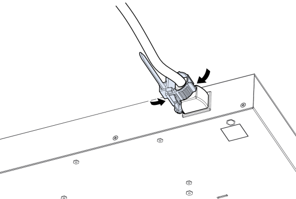
Installing the Retainer Clip
Install the retainer clip to prevent accidental removal of the power cord.
1 Loosely wrap the clip on the retainer to the power cord.
2 Push the pronged-end of the retainer clip into the Retainer Holder hole until it locks into place.
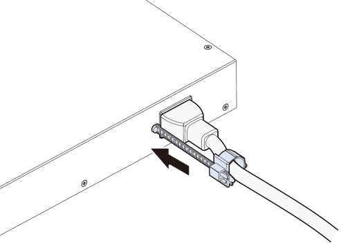
3 Slide the clip up to the end of the power cord.
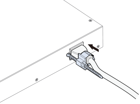
4 Close the clip tightly around the power cord until secure.
LEDs
After you connect the power to the Switch, view the LEDs to ensure proper functioning of the Switch and as an aid in troubleshooting.
LED | Color | Status | Description |
|---|---|---|---|
PWR/SYS | Green | On | The Switch is on and functioning properly. |
Blinking | The Switch is rebooting and performing self-diagnostic tests. | ||
Yellow | On | The Switch is functioning abnormally, FAN status alert/error, or the system power detected is under 10.8 V. | |
Blinking (Fast) | The Switch is returning to its custom default configuration settings. | ||
Blinking (Slow) | The Switch is returning to its factory default configuration settings. | ||
Off | The Switch is not receiving power from the power source. | ||
CLOUD | Green | On | The Switch has successfully connected to the NCC (Nebula Control Center). |
Blinking | The Switch cannot connect to the NCC because it is not registered. Please register the Switch with NCC. | ||
Yellow | On | The Switch is registered with NCC but cannot connect to the NCC. Please check the Internet connection of the Switch. | |
Blinking | The Switch is not registered with NCC and cannot connect to the NCC. Please check the Internet connection of the Switch and register the Switch with NCC. | ||
Off | The Switch is operating in standalone mode. Nebula Control Center (NCC) Discovery is disabled in SYSTEM > Cloud Management in the Switch Web Configurator. | ||
LOCATOR | Blue | On | The Switch is uploading firmware. While the Switch is doing this, do not turn off the power. |
Blinking | Shows the actual location of the Switch between several devices in a rack. The default timer is 30 minutes when you are configuring the Switch. | ||
Off | The locator is not functioning or malfunctioning. | ||
PoE MAX | Red | On | PoE power usage is more than 95 percent of the power supplied budget. |
Yellow | On | PoE power usage is below 95 percent of the power supplied budget, but over 80 percent of the power supplied budget. | |
Off | PoE power usage is below 80 percent of the power supplied budget. | ||
STACK ID | The LED is showing the Stack ID number of the Switch. ID 0 means it is a standalone Switch. | ||
PRIMARY | Green | On | The Switch is acting as a standalone switch or the master in stacking. |
Yellow | On | An error occurred when the Switch is selected as the master member in a stack. | |
Off | The Switch is acting as a non-master member in a stack. |
LED | Color | Status | Description |
|---|---|---|---|
10M/100M/1000M Base-T Ports | |||
Link / ACT 1 – 32 (XMG2230-52HP) | Green | On | The link to a 1000M Ethernet network is up. |
Blinking | The Switch is transmitting/receiving to/from a 1000M Ethernet network. | ||
Yellow | On | The link to a 10M/100M Ethernet network is up. | |
Blinking | The Switch is transmitting/receiving to/from a 10M/100M Ethernet network. | ||
Off | The link to an Ethernet network is down. | ||
100M/1000M/2.5GBase-T Ports | |||
Link / ACT 33 – 48 (XMG2230-52HP) | Green | On | The link to a 2.5 Gbps Ethernet network is up. |
Blinking | The Switch is transmitting/receiving to/from a 2.5 Gbps Ethernet network. | ||
Yellow | On | The link to a 100M/1000M Ethernet network is up. | |
Blinking | The Switch is transmitting/receiving to/from a 100M/1000M Ethernet network. | ||
Off | The link to an Ethernet network is down. | ||
100M/1000M/2.5G Base-T Ports | |||
Link / ACT 1 – 24 (XMG2230-28HP) | Green | On | The link to a 2.5 Gbps Ethernet network is up. |
Blinking | The Switch is transmitting/receiving to/from a 2.5 Gbps Ethernet network. | ||
Yellow | On | The link to a 100M/1000M Ethernet network is up. | |
Blinking | The Switch is transmitting/receiving to/from a 100M/1000M Ethernet network. | ||
Off | The link to an Ethernet network is down. | ||
PoE Mode | |||
Green | On | PoE ports can supply power to a connected PD (powered device). | |
Off | PoE ports do not supply power to a connected PD (powered device). | ||
1G/10G SFP+ Slots | |||
Link / ACT 25 – 28 (XMG2230-28HP) 49 – 52 (XMG2230-52HP) | Blue | On | The port has a successful 10G connection. |
Blinking | The port is transmitting or receiving data at 10G. | ||
Green | On | The port has a successful 1000M connection. | |
Blinking | The port is transmitting or receiving data at 1000M. | ||
Off | This link is disconnected. | ||