DHCP
DHCP Overview
This chapter shows you how to configure the DHCP feature.
DHCP (Dynamic Host Configuration Protocol RFC 2131 and RFC 2132) allows individual computers to obtain TCP/IP configuration at start-up from a server. You can configure the Switch as a DHCP server or a DHCP relay agent. When configured as a server, the Switch provides the TCP/IP configuration for the clients. If you configure the Switch as a relay agent, then the Switch forwards DHCP requests to DHCP server on your network. If you do not configure the Switch as a DHCP server or relay agent then you must have a DHCP server in the broadcast domain of the client computers or else the client computers must be configured manually.
What You Can Do
• Use the DHCPv4 Option 82 Profile screen (DHCPv4 Option 82 Profile) to create DHCPv4 option 82 profiles.
• Use the DHCPv4 Smart Relay screen (Configure a DHCPv4 Smart Relay) to configure global DHCPv4 relay. You can also use this screen to apply different DHCP option 82 profile to certain ports on the Switch.
• Use the DHCPv4 Relay VLAN Setting screen (DHCPv4 Relay VLAN Setting) to configure your DHCPv4 settings based on the VLAN domain of the DHCPv4 clients. You can also use this screen to apply a different DHCP option 82 profile to certain ports in a VLAN.
• Use the DHCPv4 Server Status Details screen (DHCPv4 Server Status Details) to view details regarding DHCP server settings configured on the Switch.
• Use the DHCPv4 Server Setup screen (DHCPv4 Server Setup) to configure DHCP server settings on the Switch.
• Use the DHCPv6 Server Status screen (DHCPv6 Server Status) to see information on the DHCPv6 server.
• Use the DHCPv6 Server Information screen (DHCPv6 Server Information) to configure DHCPv6 and DNS server settings on the Switch.
• Use the DHCPv6 Server Prefix Delegation screen (DHCPv6 Prefix Delegation) to configure DHCPv6 client and IPv6 prefix settings for a specific VLAN on the Switch.
• Use the DHCP Server Guard screen (DHCP Server Guard) to specify whether ports are trusted or untrusted ports for DHCP packets.
What You Need to Know
Read on for concepts on DHCP that can help you configure the screens in this chapter.
DHCP Modes
If there is already a DHCP server on your network, then you can configure the Switch as a DHCP relay agent. When the Switch receives a request from a computer on your network, it contacts the DHCP server for the necessary IP information, and then relays the assigned information back to the computer.
DHCPv4 Configuration Options
The DHCPv4 configuration on the Switch is divided into Smart Relay and VLAN screens. The screen you should use for configuration depends on the DHCP services you want to offer the DHCP clients on your network. Choose the configuration screen based on the following criteria:
• Smart Relay – The Switch forwards all DHCP requests to the same DHCP server.
• VLAN – The Switch is configured on a VLAN by VLAN basis. The Switch can be configured to relay DHCP requests to different DHCP servers for clients in different VLAN.
DHCPv4 Relay Status
Click NETWORKING > DHCP > DHCPv4 Relay in the navigation panel. The DHCP Relay Status screen displays.
NETWORKING > DHCP > DHCPv4 Relay > DHCP Relay Status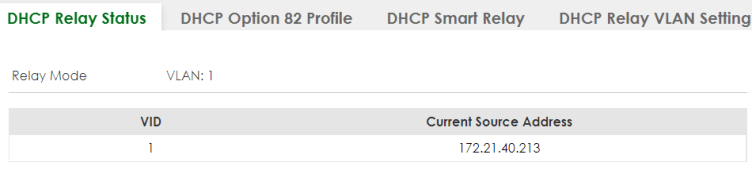
The following table describes the labels in this screen.
label | description |
|---|---|
Relay Mode | This field displays: None – if the Switch is not configured as a DHCP relay agent. Smart – if the Switch is configured as a DHCP relay agent only. VLAN – followed by a VLAN ID or multiple VLAN IDs if it is configured as a relay agent for specific VLANs. |
VID | This field displays the ID number of the VLAN for which the Switch acts as a DHCP relay agent. |
Current Source Address | This field displays the source IP address of the DHCP requests that the Switch forwards to a DHCP server. |
DHCPv4 Relay
Configure DHCP relay on the Switch if the DHCP clients and the DHCP server are not in the same broadcast domain. During the initial IP address leasing, the Switch helps to relay network information (such as the IP address and subnet mask) between a DHCP client and a DHCP server. Once the DHCP client obtains an IP address and can connect to the network, network information renewal is done between the DHCP client and the DHCP server without the help of the Switch.
The Switch can be configured as a global DHCP relay. This means that the Switch forwards all DHCP requests from all domains to the same DHCP server. You can also configure the Switch to relay DHCP information based on the VLAN membership of the DHCP clients.
DHCPv4 Relay Agent Information
The Switch can add information about the source of client DHCP requests that it relays to a DHCP server by adding Relay Agent Information. This helps provide authentication about the source of the requests. The DHCP server can then provide an IP address based on this information. Please refer to RFC 3046 for more details.
The DHCP Relay Agent Information feature adds an Agent Information field (also known as the Option 82 field) to DHCP requests. The Option 82 field is in the DHCP headers of client DHCP request frames that the Switch relays to a DHCP server.
DHCPv4 Relay Agent Information Format
A DHCP Relay Agent Information option has the following format.
Code (82) | Length (N) | i1 | i2 | ... | iN |
i1, i2 and iN are DHCP relay agent sub-options, which contain additional information about the DHCP client. You need to define at least one sub-option.
Sub-Option Format
There are two types of sub-option: “Agent Circuit ID Sub-option” and “Agent Remote ID Sub-option”. They have the following formats.
SubOpt Code | Length | Value |
1 (1 byte) | N (1 byte) | Slot ID, Port ID, VLAN ID, System Name or String |
SubOpt Code | Length | Value |
2 (1 byte) | N (1 byte) | MAC Address or String |
The 1 in the first field identifies this as an Agent Circuit ID sub-option and two identifies this as an Agent Remote ID sub-option. The next field specifies the length of the field.
DHCPv4 Option 82 Profile
Use this screen to view and configure DHCPv4 option 82 profiles. Click NETWORKING > DHCP > DHCPv4 Relay > DHCP Option 82 Profile link to display the screen as shown.
NETWORKING > DHCP > DHCPv4 Relay > DHCP Option 82 Profile
The following table describes the labels in this screen.
label | description |
|---|---|
Profile Name | This field displays the descriptive name of the profile. |
Circuit-ID | This section displays the Circuit ID sub-option including information that is specific to the relay agent (the Switch). |
Enable | This field displays whether the Circuit ID sub-option is added to client DHCP requests. |
Field | This field displays the information that is included in the Circuit ID sub-option. |
Remote-ID | This section displays the Remote ID sub-option including information that identifies the relay agent (the Switch). |
Enable | This field displays whether the Remote ID sub-option is added to client DHCP requests. |
Field | This field displays the information that is included in the Remote ID sub-option. |
Select an entry’s checkbox to select a specific entry. Otherwise, select the checkbox in the table heading row to select all entries. | |
Add/Edit | Click Add/Edit to add a new entry or edit a selected one. |
Delete | Click Delete to remove the selected entries. |
Add/Edit a DHCPv4 Option 82 Profile
Use this screen to create DHCPv4 option 82 profiles. Click Add/Edit, or select an entry and click Add/Edit in the NETWORKING > DHCP > DHCPv4 Relay > DHCP Option 82 Profile link to display this screen.
NETWORKING > DHCP > DHCPv4 Relay > DHCP Option 82 Profile > Add/Edit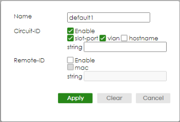
 The string of any field in this screen should not contain [ ? ], [ | ], [ ' ], [ " ], or [ , ].
The following table describes the labels in this screen.
label | description |
|---|---|
Name | Enter a descriptive name for the profile for identification purposes. You can use up to 32 printable ASCII characters. |
Circuit-ID | Use this section to configure the Circuit ID sub-option to include information that is specific to the relay agent (the Switch). |
Enable | Select this option to have the Switch add the Circuit ID sub-option to client DHCP requests that it relays to a DHCP server. |
slot-port | Select this option to have the Switch add the number of port that the DHCP client is connected to. |
vlan | Select this option to have the Switch add the ID of VLAN which the port belongs to. |
hostname | This is the system name you configure in the SYSTEM > General Setup > General Setup screen. Select this option for the Switch to add the system name to the client DHCP requests that it relays to a DHCP server. |
string | Enter a string of up to 64 printable ASCII characters that the Switch adds into the client DHCP requests. |
Remote-ID | Use this section to configure the Remote ID sub-option to include information that identifies the relay agent (the Switch). |
Enable | Select this option to have the Switch append the Remote ID sub-option to the option 82 field of DHCP requests. |
mac | Select this option to have the Switch add its MAC address to the client DHCP requests that it relays to a DHCP server. |
string | Enter a string of up to 64 printable ASCII characters for the remote ID information in this field. |
Apply | Click Apply to save your changes to the Switch’s run-time memory. The Switch loses these changes if it is turned off or loses power, so use the Save link on the top navigation panel to save your changes to the non-volatile memory when you are done configuring. |
Clear | Click Clear to clear the fields to the factory defaults. |
Cancel | Click Cancel to not save the configuration you make and return to the last screen. |
Configure a DHCPv4 Smart Relay
Use this screen to configure global DHCPv4 relay. Click NETWORKING > DHCP > DHCPv4 Relay > DHCP Smart Relay to display the screen as shown.
NETWORKING > DHCP > DHCPv4 Relay > DHCP Smart Relay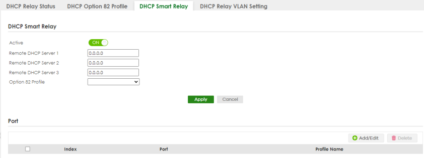
The following table describes the labels in this screen.
label | description |
|---|---|
DHCP Smart Relay | |
Active | Select this checkbox to enable DHCPv4 relay. |
Remote DHCP Server 1 .. 3 | Enter the IP address of a DHCPv4 server in dotted decimal notation. |
Option 82 Profile | Select a pre-defined DHCPv4 option 82 profile that the Switch applies to all ports. The Switch adds the Circuit ID sub-option and/or Remote ID sub-option specified in the profile to DHCP requests that it relays to a DHCP server. |
Apply | Click Apply to save your changes to the Switch’s run-time memory. The Switch loses these changes if it is turned off or loses power, so use the Save link on the top navigation panel to save your changes to the non-volatile memory when you are done configuring. |
Cancel | Click Cancel to begin configuring this screen afresh. |
Port Use this section to apply a different DHCP option 82 profile to certain ports on the Switch. | |
Index | This field displays a sequential number for each entry. |
Port | This field displays the ports to which the Switch applies the settings. |
Profile Name | This field displays the DHCP option 82 profile that the Switch applies to the ports. |
Select an entry’s checkbox to select a specific entry. Otherwise, select the checkbox in the table heading row to select all entries. | |
Add/Edit | Click Add/Edit to add a new entry or edit a selected one. |
Delete | Click Delete to remove the selected entries. |
Add/Edit DHCPv4 Global Relay Port
Use this screen to apply a different DHCP option 82 profile to certain ports on the Switch. To open this screen, Click Add/Edit, or select an entry and click Add/Edit in the Port section of the NETWORKING > DHCP > DHCPv4 Relay > DHCP Smart Relay screen.
NETWORKING > DHCP > DHCPv4 Relay > DHCP Smart Relay > Add/Edit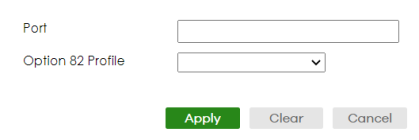
The following table describes the labels in this screen.
label | description |
|---|---|
Port | Enter the number of ports to which you want to apply the specified DHCP option 82 profile. You can enter multiple ports separated by (no space) comma (,) or hyphen (-). For example, enter “3-5” for ports 3, 4, and 5. Enter “3,5,7” for ports 3, 5, and 7. |
Option 82 Profile | Select a pre-defined DHCP option 82 profile that the Switch applies to the specified ports. The Switch adds the Circuit ID sub-option and/or Remote ID sub-option specified in the profile to DHCP requests that it relays to a DHCP server. The profile you select here has priority over the one you select in the NETWORKING > DHCP > DHCPv4 Relay > DHCPv4 Smart Relay screen. |
Apply | Click Apply to save your changes to the Switch’s run-time memory. The Switch loses these changes if it is turned off or loses power, so use the Save link on the top navigation panel to save your changes to the non-volatile memory when you are done configuring. |
Clear | Click Clear to clear the fields to the factory defaults. |
Cancel | Click Cancel to not save the configuration you make and return to the last screen. |
DHCP Smart Relay Configuration Example
The follow figure shows a network example where the Switch is used to relay DHCP requests for the VLAN1 and VLAN2 domains. There is only one DHCP server (S) that services the DHCP clients in both domains.
DHCP Smart Relay Network Example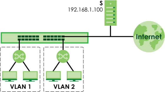
Configure the NETWORKING > DHCP > DHCPv4 Relay > DHCP Smart Relay screen as shown. Make sure you select a DHCP option 82 profile (default1 in this example) to set the Switch to send additional information (such as the VLAN ID) together with the DHCP requests to the DHCP server. This allows the DHCP server to assign the appropriate IP address according to the VLAN ID. Click Apply after you finish the configuration.
DHCP Relay Configuration Example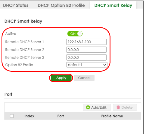
DHCPv4 Relay VLAN Setting
Use this screen to configure your DHCP settings based on the VLAN domain of the DHCP clients. Click NETWORKING > DHCP > DHCPv4 Relay > DHCP Relay VLAN Setting to display the screen as shown.
NETWORKING > DHCP > DHCPv4 Relay > DHCP Relay VLAN Setting 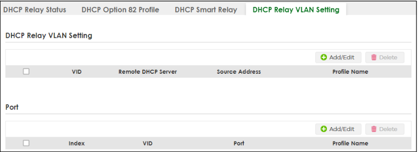
The following table describes the labels in this screen.
label | description |
|---|---|
DHCP Relay VLAN Setting | |
VID | This field displays the ID number of the VLAN group to which this DHCP settings apply. |
Remote DHCP Server | This displays the IP address of a DHCP server in dotted decimal notation. |
Source Address | This field displays the source IP address you configured for DHCP requests from clients on this VLAN. |
Profile Name | This field displays the DHCP option 82 profile that the Switch applies to this VLAN. |
Select an entry’s checkbox to select a specific entry. Otherwise, select the checkbox in the table heading row to select all entries. | |
Add/Edit | Click Add/Edit to add a new entry or edit a selected one. |
Delete | Click Delete to remove the selected entries. |
Port Use this section to apply a different DHCP option 82 profile to certain ports in a VLAN. | |
Index | This field displays a sequential number for each entry. Click an index number to change the settings. |
VID | This field displays the VLAN to which the ports belongs. |
Port | This field displays the ports to which the Switch applies the settings. |
Profile Name | This field displays the DHCP option 82 profile that the Switch applies to the ports in this VLAN. |
Select an entry’s checkbox to select a specific entry. Otherwise, select the checkbox in the table heading row to select all entries. | |
Add/Edit | Click Add/Edit to add a new entry or edit a selected one. |
Delete | Click Delete to remove the selected entries. |
Add/Edit DHCPv4 VLAN Setting
Use this screen to add/edit your DHCP settings based on the VLAN domain of the DHCP clients. Click the Add/Edit button in the DHCP Relay VLAN Setting section of the NETWORKING > DHCP > DHCPv4 Relay > DHCP Relay VLAN Setting screen to access this screen.
You must set up a management IP address for each VLAN that you want to configure DHCP settings for on the Switch.NETWORKING > DHCP > DHCPv4 Relay > DHCP Relay VLAN Setting > Add/Edit (DHCP Relay VLAN Setting)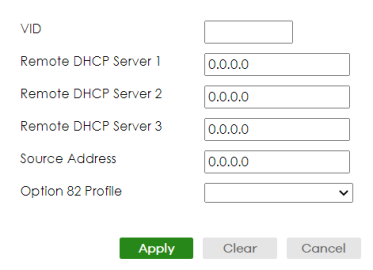
The following table describes the labels in this screen.
label | description |
|---|---|
VID | Enter the ID number of the VLAN to which these DHCP settings apply. |
Remote DHCP Server 1 .. 3 | Enter the IP address of a DHCP server in dotted decimal notation. |
Source Address | Enter the source IP address that the Switch adds to DHCP requests from clients on this VLAN before forwarding them. If you leave this field set to 0.0.0.0, the Switch automatically sets the source IP address of the DHCP requests to the IP address of the interface on which the packet is received. The source IP address helps DHCP clients obtain an appropriate IP address when you configure multiple routing domains on a VLAN. |
Option 82 Profile | Select a pre-defined DHCP option 82 profile that the Switch applies to all ports in this VLAN. The Switch adds the Circuit ID sub-option and/or Remote ID sub-option specified in the profile to DHCP requests that it relays to a DHCP server. |
Apply | Click Apply to save your changes to the Switch’s run-time memory. The Switch loses these changes if it is turned off or loses power, so use the Save link on the top navigation panel to save your changes to the non-volatile memory when you are done configuring. |
Clear | Click Clear to clear the fields to the factory defaults. |
Cancel | Click Cancel to not save the configuration you make and return to the last screen. |
Add/Edit DHCPv4 VLAN Port
Use this screen to apply a different DHCP option 82 profile to certain ports in a VLAN. Click the Add/Edit button in the Port section of the NETWORKING > DHCP > DHCPv4 Relay > DHCP Relay VLAN Setting screen to access this screen.
NETWORKING > DHCP > DHCPv4 Relay > DHCP Relay VLAN Setting > Add/Edit (Port)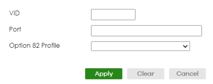
The following table describes the labels in this screen.
label | description |
|---|---|
VID | Enter the ID number of the VLAN you want to configure here. |
Port | Enter the number of ports to which you want to apply the specified DHCP option 82 profile. You can enter multiple ports separated by (no space) comma (,) or hyphen (-). For example, enter “3-5” for ports 3, 4, and 5. Enter “3,5,7” for ports 3, 5, and 7. |
Option 82 Profile | Select a pre-defined DHCP option 82 profile that the Switch applies to the specified ports in this VLAN. The Switch adds the Circuit ID sub-option and/or Remote ID sub-option specified in the profile to DHCP requests that it relays to a DHCP server. The profile you select here has priority over the one you select in the NETWORKING > DHCP > DHCPv4 Relay > DHCP Relay VLAN Setting (the DHCP Relay VLAN Setting section)> Add/Edit screen. |
Apply | Click Apply to save your changes to the Switch’s run-time memory. The Switch loses these changes if it is turned off or loses power, so use the Save link on the top navigation panel to save your changes to the non-volatile memory when you are done configuring. |
Clear | Click Clear to clear the fields to the factory defaults. |
Cancel | Click Cancel to not save the configuration you make and return to the last screen. |
DHCPv4 Server Status
Click NETWORKING > DHCP > DHCPv4 Server in the navigation panel. The DHCP Server Status screen displays.
NETWORKING > DHCP > DHCPv4 Server > DHCP Server Status
The following table describes the labels in this screen.
label | description |
|---|---|
Server Status This section displays configuration settings related to the Switch’s DHCP Server mode. | |
Index | This is the index number. Click an index number to view the server configuration details. |
VID | This field displays the VLAN ID for which the Switch is a DHCP server. |
Server Status | This field displays the starting DHCP client IP address. |
IP Pool Size | This field displays the number of IP addresses that can be assigned to clients. |
DHCPv4 Server Status Details
Click an existing index number of a DHCP server configuration in the NETWORKING > DHCP > DHCPv4 Server > DHCPv4 Server Status screen to display the screen as shown. Use this screen to view details regarding DHCP server settings configured on the Switch.
NETWORKING > DHCP > DHCPv4 Server > DHCP Server Status > Server Status Details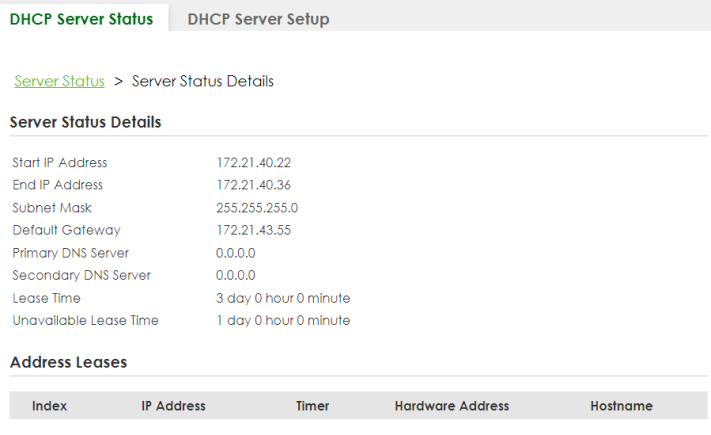
The following table describes the labels in this screen.
Label | description |
|---|---|
Server Status Details This section displays the configuration details of this DHCP server. You can change the DHCP server configuration in the NETWORKING > DHCP > DHCPv4 Server > DHCP Server Setup screen. | |
Start IP Address | This field displays the starting IP address of the IP address pool configured for this DHCP server instance. |
End IP Address | This field displays the last IP address of the IP address pool configured for this DHCP server instance. |
Subnet Mask | This field displays the subnet mask value sent to clients from this DHCP server instance. |
Default Gateway | This field displays the default gateway value sent to clients from this DHCP server instance. |
Primary DNS Server | This field displays the primary DNS server value sent to clients from this DHCP server instance. |
Secondary DNS Server | This field displays the secondary DNS server value sent to clients from this DHCP server instance. |
Lease Time | This field displays the amount of time that the IP address is valid. |
Unavailable Lease Time | This field display the lease time of the unavailable IP addresses occupied by unknown hosts. |
Address Leases This section displays information about the IP addresses this DHCP server issued to clients. | |
Index | This field displays a sequential number for each DHCP request handled by the Switch. |
IP Address | This is the IP address issued to a DHCP client. |
Timer | This field displays the time remaining before the DHCP client has to renew its IP address. |
Hardware Address | This field displays the MAC address of the DHCP client. It may also display SELF OCCUPIED ADDRESS if the IP address cannot be used for DHCP because it is already assigned to the Switch itself. |
Hostname | This field displays the system name of the client. |
DHCPv4 Server Setup
Use this screen to view and configure the DHCP server settings. The Switch serves as a DHCP server (DHCP server mode) when you add a configuration entry in this screen. Click NETWORKING > DHCP > DHCPv4 Server > DHCP Server Setup to display the screen as shown.
NETWORKING > DHCP > DHCPv4 Server > DHCP Server Setup
The following table describes the labels in this screen.
label | description |
|---|---|
VID | This field displays the ID number of the VLAN group to which this DHCP settings apply. |
Starting Address | This field displays the starting IP address of the IP address pool configured for the DHCP server. |
Size of IP Pool | This field displays the IP address pool size of the DHCP server. |
Select an entry’s checkbox to select a specific entry. Otherwise, select the checkbox in the table heading row to select all entries. | |
Add/Edit | Click Add/Edit to add a new entry or edit a selected one. |
Delete | Click Delete to remove the selected entries. |
Add/Edit DHCPv4 Server
Use this screen to configure the DHCP server settings. Click Add/Edit, or select an entry and click Add/Edit in the NETWORKING > DHCP > DHCPv4 Server > DHCP Server Setup to display this screen.
NETWORKING > DHCP > DHCPv4 Server > DHCP Server Setup > Add/Edit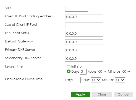
The following table describes the labels in this screen.
label | description |
|---|---|
VID | Enter the ID number of the VLAN to which these DHCP settings apply. |
Client IP Pool Starting Address | Specify the first of the contiguous addresses in the IP address pool. |
Size of Client IP Pool | Specify the size, or count of the IP address pool. The Switch can issue from 1 to 253 IP addresses to DHCP clients. |
IP Subnet Mask | Enter the subnet mask for the client IP pool. |
Default Gateway | Enter the IP address of the default gateway device. |
Primary/ Secondary DNS Server | Enter the IP addresses of the DNS servers. The DNS servers are passed to the DHCP clients along with the IP address and the subnet mask. |
Lease Time | Select Infinite to have the binding always valid. Select the second radio button to set up the binding’s valid days, hours and minutes. |
Unavailable Lease Time | Unavailable lease time is the lease time of an IP address that is distributed by other unknown DHCP servers to other devices. A DHCP client rejects the IP address assigned by the Switch when it discovers the assigned IP is already in use by other devices. When an IP is in use by other devices, the Switch cannot assign this unavailable IP to the Switch’s DHCP client. The Switch will mark the IP as an unavailable IP and removes it from the IP address pool. The Switch will not assign the unavailable IP to DHCP clients until Unavailable Lease Time expires. Set up the days, hours, and minutes of unavailable lease time. |
DHCPv6 Relay
A DHCPv6 relay agent is on the same network as the DHCPv6 clients and helps forward messages between the DHCPv6 server and clients. When a client cannot use its link-local address and a well-known multicast address to locate a DHCPv6 server on its network, it then needs a DHCPv6 relay agent to send a message to a DHCPv6 server that is not attached to the same network.
A DHCPv6 relay agent is on the same network as the DHCPv6 clients and helps forward messages between the DHCPv6 server (that is in another network) and the DHCPv6 clients.
The DHCPv6 relay agent can add the remote identification (remote-ID) option and the interface-ID option to the Relay-Forward DHCPv6 messages. The remote-ID option carries a user-defined string, such as the system name. The interface-ID option provides slot number, port information and the VLAN ID to the DHCPv6 server. The remote-ID option (if any) is stripped from the Relay-Reply messages before the relay agent sends the packets to the clients. The DHCPv6 server copies the interface-ID option from the Relay-Forward message into the Relay-Reply message and sends it to the relay agent. The interface-ID should not change even after the relay agent restarts.
Use this screen to view and configure DHCPv6 relay settings for a specific VLAN on the Switch. Click NETWORKING > DHCP > DHCPv6 Relay > DHCPv6 Relay in the navigation panel to display the screen as shown.
NETWORKING > DHCP > DHCPv6 Relay > DHCPv6 Relay
The following table describes the labels in this screen.
label | description |
|---|---|
VID | This field displays the VLAN ID number. |
Helper Address | This field displays the IPv6 address of the remote DHCPv6 server for this VLAN. |
Interface ID | This field displays whether the interface-ID option is added to DHCPv6 requests from clients in this VLAN. |
Remote ID | This field displays whether the remote-ID option is added to DHCPv6 requests from clients in this VLAN. |
Select an entry’s checkbox to select a specific entry. Otherwise, select the checkbox in the table heading row to select all entries. | |
Add/Edit | Click Add/Edit to add a new entry or edit a selected one. |
Delete | Click Delete to remove the selected entries. |
Add/Edit DHCPv6 Relay
Use this screen to add/edit DHCPv6 relay settings for a specific VLAN on the Switch. Click Add/Edit, or select an entry and click Add/Edit in the NETWORKING > DHCP > DHCPv6 Relay > DHCPv6 Relay screen to display this screen.
NETWORKING > DHCP > DHCPv6 Relay > DHCPv6 Relay > Add/Edit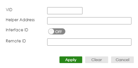
The following table describes the labels in this screen.
label | description |
|---|---|
VID | Enter the ID number of the VLAN to which the DHCPv6 server that will assign IP information belongs here. |
Helper Address | Enter the IPv6 address of the DHCPv6 server that will assign IP information here. An 128-bit IPv6 address is written as eight 16-bit hexadecimal blocks separated by colons (:). This is an example IPv6 address ‘2001:0db8:1a2b:0015:0000:0000:1a2f:0000’. IPv6 addresses can be abbreviated in two ways: • Leading zeros in a block can be omitted. So ‘2001:0db8:1a2b:0015:0000:0000:1a2f:0000’ can be written as ‘2001:db8:1a2b:15:0:0:1a2f:0’. • Any number of consecutive blocks of zeros can be replaced by a double colon. A double colon can only appear once in an IPv6 address. So ‘2001:0db8:0000:0000:1a2f:0000:0000:0015’ can be written as ‘2001:0db8::1a2f:0000:0000:0015’, ‘2001:0db8:0000:0000:1a2f::0015’, ‘2001:db8::1a2f:0:0:15’ or ‘2001:db8:0:0:1a2f::15’. |
Interface ID | Enable the switch button to have the Switch add the interface-ID option in the DHCPv6 requests from the clients in the specified VLAN before the Switch forwards them to a DHCPv6 server. |
Remote ID | Enter a string of up to 64 printable ASCII characters (except [ ? ], [ | ], [ ' ], or [ " ]) to be carried in the remote-ID option. The Switch adds the remote-ID option in the DHCPv6 requests from the clients in the specified VLAN before the Switch forwards them to a DHCPv6 server. |
Apply | Click Apply to save your changes to the Switch’s run-time memory. The Switch loses these changes if it is turned off or loses power, so use the Save link on the top navigation panel to save your changes to the non-volatile memory when you are done configuring. |
Clear | Click Clear to clear the fields to the factory defaults. |
Cancel | Click Cancel to not save the configuration you make and return to the last screen. |
DHCPv6 Server Status
Click NETWORKING > DHCP > DHCPv6 Server > DHCPv6 Server Status to see information on the DHCPv6 server.
NETWORKING > DHCP > DHCPv6 Server > DHCPv6 Server Status
The following table describes the labels in this screen.
Label | description |
|---|---|
Index | This is the index number of a DHCPv6 server information. |
VID | This field displays the VLAN ID to which the DHCP server belongs. |
Information | This field displays Yes when the entry supports display of the refresh time and DNS server; it shows No when it does not. |
Prefix Delegation | This field displays Yes when the entry supports the prefix delegation; it shows No when it does not. The prefix delegation is used by an IPv6 device to generate its IP address. |
DHCPv6 Server Information
Use this screen to view and configure DHCPv6 and DNS server settings on the Switch. Click NETWORKING > DHCP > DHCPv6 Server > DHCPv6 Server Information to display the screen as shown.
NETWORKING > DHCP > DHCPv6 Server > DHCPv6 Server Information
The following table describes the labels in this screen.
Label | description |
|---|---|
Index | This field displays a sequential number for each entry. |
Active | This field displays whether the entry is activated or not. |
VID | This field displays the ID number of the VLAN to which the DHCPv6 server belongs. |
Refresh Time | This field displays the number of seconds a DHCPv6 client should wait before refreshing information retrieved from a DHCPv6 server. It displays disable if Refresh Time is not configured. |
DNS Server | This field displays the IPv6 address of the DNS server that the DHCP clients will use. It displays disable when it is not configured. |
Select an entry’s checkbox to select a specific entry. Otherwise, select the checkbox in the table heading row to select all entries. | |
Add/Edit | Click Add/Edit to add a new entry or edit a selected one. |
Delete | Click Delete to remove the selected entries. |
Add/Edit DHCPv6 Server Information
Use this screen to add/edit DHCPv6 and DNS server settings on the Switch. Click Add/Edit, or select an entry and click Add/Edit in the NETWORKING > DHCP > DHCPv6 Server > DHCPv6 Server Information to display this screen.
NETWORKING > DHCP > DHCPv6 Server > DHCPv6 Server Information > Add/Edit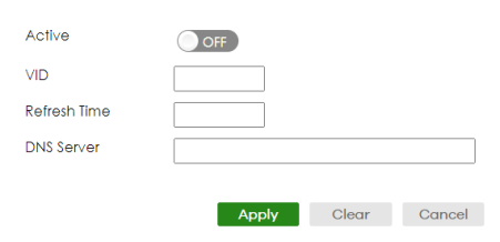
The following table describes the labels in this screen.
Label | description |
|---|---|
Active | Enable the switch button to enable the entry. |
VID | Enter the ID number of the VLAN to which the DHCPv6 server belongs here. |
Refresh Time | Enter the number of seconds a DHCPv6 client should wait before refreshing information retrieved from a DHCPv6 server. The allowed range is 600 to 4294967295 seconds. |
DNS Server | Specify the IPv6 address of the DNS server for the DHCP clients to use here. An 128-bit IPv6 address is written as eight 16-bit hexadecimal blocks separated by colons (:). This is an example IPv6 address ‘2001:0db8:1a2b:0015:0000:0000:1a2f:0000’. IPv6 addresses can be abbreviated in two ways: • Leading zeros in a block can be omitted. So ‘2001:0db8:1a2b:0015:0000:0000:1a2f:0000’ can be written as ‘2001:db8:1a2b:15:0:0:1a2f:0’. • Any number of consecutive blocks of zeros can be replaced by a double colon. A double colon can only appear once in an IPv6 address. So ‘2001:0db8:0000:0000:1a2f:0000:0000:0015’ can be written as ‘2001:0db8::1a2f:0000:0000:0015’, ‘2001:0db8:0000:0000:1a2f::0015’, ‘2001:db8::1a2f:0:0:15’ or ‘2001:db8:0:0:1a2f::15’. |
Apply | Click Apply to save your changes to the Switch’s run-time memory. The Switch loses these changes if it is turned off or loses power, so use the Save link on the top navigation panel to save your changes to the non-volatile memory when you are done configuring. |
Clear | Click Clear to clear the fields to the factory defaults. |
Cancel | Click Cancel to not save the configuration you make and return to the last screen. |
DHCPv6 Prefix Delegation
Prefix delegation enables an IPv6 device to use the received IPv6 prefix (for example, ‘2001:db2::/48’) to generate its IP address. The Switch passes the IPv6 prefix information to its connected hosts (according to VLAN) so that they can generate their IPv6 addresses.
Use this screen to view and configure DHCPv6 client and IPv6 prefix settings for a specific VLAN on the Switch. Click NETWORKING > DHCP > DHCPv6 Server > DHCPv6 Server Prefix Delegation to display the screen as shown.
NETWORKING > DHCP > DHCPv6 Server > DHCPv6 Server Prefix Delegation
The following table describes the labels in this screen.
Label | description |
|---|---|
Index | This field displays a sequential number for each entry. |
Client DUID | This field displays the client DHCP Unique IDentifier (DUID) which uniquely identifies the client. |
Client Name | This field displays a name to identify the DHCPv6 client. |
VID | This field displays the ID number of the VLAN to which the DHCPv6 client belongs. |
Select an entry’s checkbox to select a specific entry. Otherwise, select the checkbox in the table heading row to select all entries. | |
Add/Edit | Click Add/Edit to add a new entry or edit a selected one. |
Delete | Click Delete to remove the selected entries. |
Add/Edit DHCPv6 Prefix Delegation
Use this screen to add/edit DHCPv6 client and IPv6 prefix settings for a specific VLAN on the Switch. Click Add/Edit, or select an entry and click Add/Edit in the NETWORKING > DHCP > DHCPv6 Server > DHCPv6 Server Prefix Delegation screen to display this screen.
NETWORKING > DHCP > DHCPv6 Server > DHCPv6 Server Prefix Delegation > Add/Edit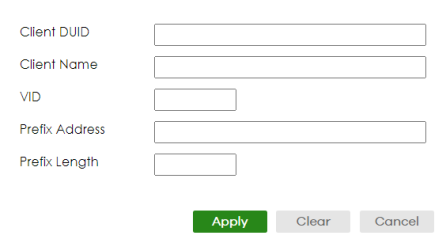
The following table describes the labels in this screen.
Label | description |
|---|---|
Client DUID | Each DHCP client and server has a unique DHCP Unique IDentifier (DUID), which is used for identification when they are exchanging DHCPv6 messages. The DUID is generated from the MAC address, time, vendor assigned ID and/or the vendor's private enterprise number registered with the IANA. Type the client DUID for the devices connected to the Switch in this field. |
Client Name | Type a name to identify the DHCPv6 client in this field. You can enter up to 64 printable ASCII characters except [ ? ], [ | ], [ ' ], [ " ] or [ , ]. |
VID | Type the ID number of the VLAN to which the DHCPv6 client belongs here. |
Prefix Address | IPv6 uses an address prefix to represent the network address. An IPv6 prefix length specifies how many most significant bits (start from the left) in the address compose the network address. The prefix length is written as “/x” where x is a number. For example, ‘2001:db8:1a2b:15::1a2f:0/32’ is a prefix address with prefix length. /32 means that the first 32 bits (‘2001:db8’) from the left is the network prefix. Type the prefix address in this field. For example, type ‘2001:db8:1a2b:15::1a2f:0’ |
Prefix Length | Type the prefix length in this field. For example, type 32. |
DHCP Server Guard
Use this screen to specify whether ports are trusted or untrusted ports for DHCP packets. Click NETWORKING > DHCP > DHCP Server Guard > DHCP Server Guard in the navigation panel to display the screen as shown.
NETWORKING > DHCP > DHCP Server Guard > DHCP Server Guard (Standalone Mode)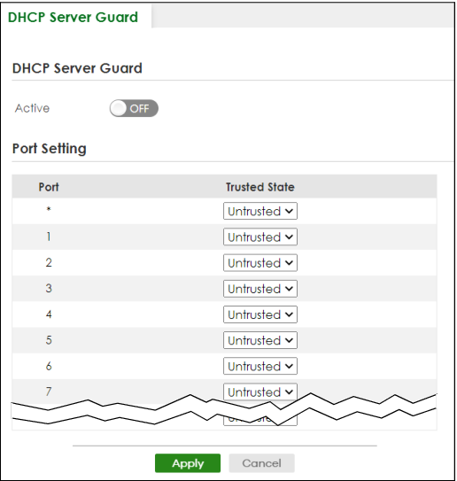
The following table describes the labels in this screen.
label | description |
|---|---|
DHCP Server Guard | |
Active | Enable the switch button to enable DHCP Server Guard. |
Port Setting | |
Port | The port number identifies the port you are configuring. |
* | Settings in this row apply to all ports. Use this row only if you want to make some settings the same for all ports. Use this row first to set the common settings and then make adjustments on a port-by-port basis. Changes in this row are copied to all the ports as soon as you make them. |
Trusted State | Select whether this port is a trusted port (Trusted) or an untrusted port (Untrusted). The Switch does not discard DHCP packets on trusted ports for any reason. The Switch discards DHCP packets from untrusted ports when the packet is a DHCP server packet (for example, OFFER, ACK, or NACK). |
Apply | Click Apply to save your changes to the Switch’s run-time memory. The Switch loses these changes if it is turned off or loses power, so use the Save link on the top navigation panel to save your changes to the non-volatile memory when you are done configuring. |
Cancel | Click Cancel to reset the fields to their last saved values. |