Static Route
Static Routing Overview
This chapter shows you how to configure static routes.
IP static routes are used by layer-2 Switches to ensure they can respond to management stations not reachable through the default gateway and to proactively send traffic, for example when sending SNMP traps or conducting IP connectivity tests using ping.
For example, the next figure shows a computer (A) connected to the Switch. The Switch routes most traffic from A to the Internet through the Switch’s default gateway (R1). You create one static route to connect to services offered by your ISP behind router R2. You create another static route to communicate with a separate network behind a router R3 connected to the Switch.
Example of Static Routing Topology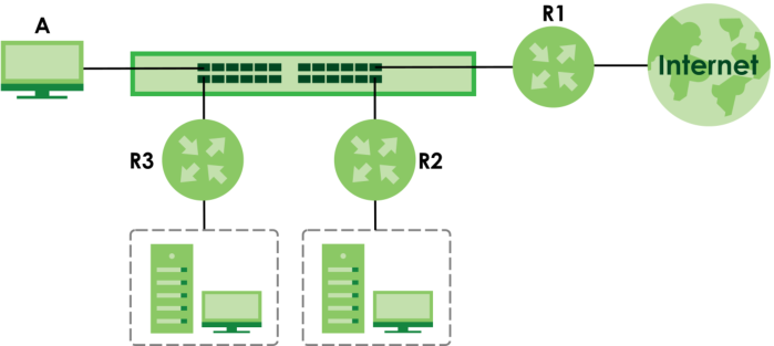
What You Can Do
Use the IPv4 Static Route screen (IPv4 Static Route) to configure and enable an IPv4 static route.
Use the IPv6 Static Route screen (IPv6 Static Route) to configure and enable an IPv6 static route.
IPv4 Static Route
Click NETWORKING > Static Routing > IPv4 Static Route > IPv4 Static Route to display the screen as shown.
NETWORKING > Static Routing > IPv4 Static Route > IPv4 Static Route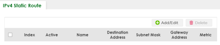
The following table describes the related labels you use to create a static route.
LABEL | DESCRIPTION |
|---|---|
Index | This field displays the index number of the route. |
Active | This field displays whether the static route is activated or not. |
Name | This field displays the descriptive name for this route. This is for identification purposes only. |
Destination Address | This field displays the IP network address of the final destination. |
Subnet Mask | This field displays the subnet mask for this destination. |
Gateway Address | This field displays the IP address of the gateway. The gateway is an immediate neighbor of your Switch that will forward the packet to the destination. |
Metric | This field displays the cost of transmission for routing purposes. |
Select an entry’s checkbox to select a specific entry. Otherwise, select the checkbox in the table heading row to select all entries. | |
Add/Edit | Click Add/Edit to add a new entry or edit a selected one. |
Delete | Click Delete to remove the selected entries. |
Add/Edit IPv4 Static Route
Click Add/Edit, or select an entry and click Add/Edit in the NETWORKING > Static Routing > IPv4 Static Route > IPv4 Static Route screen to display this screen.
NETWORKING > Static Routing > IPv4 Static Route > IPv4 Static Route > Add/Edit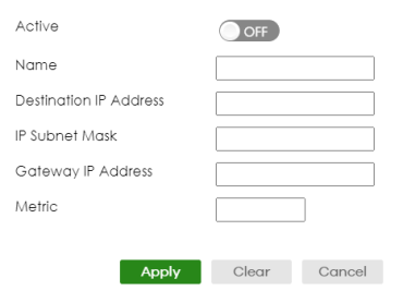
The following table describes the related labels you use to create a static route.
LABEL | DESCRIPTION |
|---|---|
Active | This field allows you to activate or deactivate this static route. |
Name | Enter a descriptive name (up to 10 printable ASCII characters except [ ? ], [ | ], [ ' ], or [ " ]) for identification purposes. |
Destination IP Address | This parameter specifies the IP network address of the final destination. |
IP Subnet Mask | Enter the subnet mask for this destination. Routing is always based on network number. If you need to specify a route to a single host, use a subnet mask of 255.255.255.255 in the subnet mask field to force the network number to be identical to the host ID. |
Gateway IP Address | Enter the IP address of the gateway. The gateway is an immediate neighbor of your Switch that will forward the packet to the destination. The gateway must be a router on the same segment as your Switch. |
Metric | The metric represents the “cost” of transmission for routing purposes. IP routing uses hop count as the measurement of cost, with a minimum of 1 for directly connected networks. Enter a number that approximates the cost for this link. The number need not be precise, but it must be between 1 and 15. In practice, 2 or 3 is usually a good number. |
Apply | Click Apply to save your changes to the Switch’s run-time memory. The Switch loses these changes if it is turned off or loses power, so use the Save link on the top navigation panel to save your changes to the non-volatile memory when you are done configuring. |
Clear | Click Clear to clear the fields to the factory defaults. |
Cancel | Click Cancel to not save the configuration you make and return to the last screen. |
IPv6 Static Route
Click NETWORKING > Static Routing > IPv6 Static Route > IPv6 Static Route to display the screen as shown.
NETWORKING > Static Routing > IPv6 Static Route > IPv6 Static Route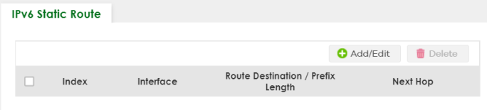
The following table describes the related labels you use to create a static route.
LABEL | DESCRIPTION |
|---|---|
Index | This field displays the index number of the route. |
Interface | This field displays the descriptive name of the interface that is used to forward the packets to the destination. |
Route Destination / Prefix Length | This field displays the IPv6 subnet prefix and prefix length of the final destination. |
Next Hop | This field displays the IPv6 address of the gateway that helps forward the packet to the destination. |
Select an entry’s checkbox to select a specific entry. Otherwise, select the checkbox in the table heading row to select all entries. | |
Add/Edit | Click Add/Edit to add a new entry or edit a selected one. |
Delete | Click Delete to remove the selected entries. |
Add/Edit IPv6 Static Route
Click Add/Edit, or select an entry and click Add/Edit in the NETWORKING > Static Routing > IPv6 Static Route > IPv6 Static Route to display this screen.
NETWORKING > Static Routing > IPv6 Static Route > IPv6 Static Route > Add/Edit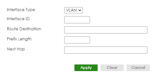
The following table describes the related labels you use to create a static route.
LABEL | DESCRIPTION |
|---|---|
Interface Type | Select the type of the IPv6 interface through which the IPv6 packets are forwarded. The Switch supports only the VLAN interface type at the time of writing. |
Interface ID | Enter the ID number of the IPv6 interface through which the IPv6 packets are forwarded. |
Route Destination | Enter the IPv6 address of the final destination. |
Prefix Length | Enter the prefix length number of up to 64 for this destination. |
Next Hop | Enter the IPv6 address of the next-hop router. |
Apply | Click Apply to save your changes to the Switch’s run-time memory. The Switch loses these changes if it is turned off or loses power, so use the Save link on the top navigation panel to save your changes to the non-volatile memory when you are done configuring. |
Clear | Click Clear to clear the fields to the factory defaults. |
Cancel | Click Cancel to not save the configuration you make and return to the last screen. |