Auto PD Recovery
Auto PD Recovery (for PoE models only) Overview
Things can go wrong with any network devices. A PD (for example, IP camera) may slow down or freeze and need to be restarted if it is overworked or a bug causes a memory leak. When a connected PD ceases to respond, Automatic PD Recovery allows the Switch to restart the PD by turning it off and on without the need for on-site troubleshooting.
What You Can Do
Use the Auto PD Recovery screen (Auto PD Recovery) to enable and configure automatic PD recovery on the Switch.
Auto PD Recovery
This screen lets you turn on automatic PD recovery on the Switch and its Ethernet ports. You can configure whether the Switch uses LLDP or ping to check the current status of a connected PD.
The ping is sent through the Switch's default management IP address to the designated port. To ping the PD, the port must share the same VLAN as the Switch's management VLAN.
Auto PD Recovery Application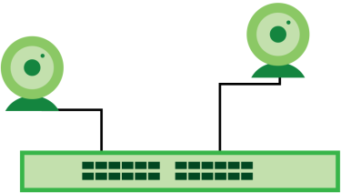
The PD may stop responding to the Switch’s detection over ping or LLDP during firmware upgrade. Disable the Auto PD Recovery function to prevent damage to the PD caused by a power cutoff during firmware upgrade.
 The following screens are available for the PoE models only.
To open this screen, click PORT > Auto PD Recovery > Auto PD Recovery.
PORT > Auto PD Recovery > Auto PD Recovery (Standalone Mode)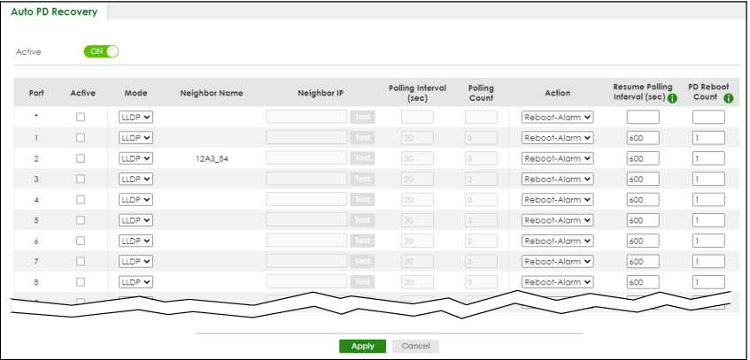
The following table describes the labels in this screen.
label | description |
|---|---|
Active | Select this option to enable Auto PD Recovery on the Switch. |
Port | This field displays the index number of a port on the Switch. |
* | Settings in this row apply to all ports. Use this row only if you want to make some settings the same for all ports. Use this row first to set the common settings and then make adjustments on a port-by-port basis. Changes in this row are copied to all the ports as soon as you make them. |
Active | Select Active to enable Auto PD Recovery on the ports. |
Mode | Select LLDP to have the Switch passively monitor current status of the connected PD by reading LLDP packets from the PD on the port. The Switch also sends out LLDP packets to the PD to update the Switch Neighbor table on the PD. Select Ping to have the Switch ping the IP address of the connected PD to test whether the PD is reachable or not. |
Neighbor Name | If Mode is set to LLDP, the system name of the connected PD displays automatically. |
Neighbor IP | If Mode is set to Ping and the PD supports LLDP, the connected PD’s IPv4 or IPv6 address to which the Switch sends ping requests will display automatically. If not, enter the IP address manually. |
Test | Click Test to have the Switch test the connection by sending a ping request to the IP address. |
Polling Interval (sec) | Specify the number of seconds the Switch waits for a response before sending another ping request. For example, the Switch will try to detect the PD status by performing ping requests every 20 seconds. |
Polling Count | Specify how many times the Switch is to resend a ping request before considering the PD unreachable. For example, If there is no ping reply from the PD after the Polling Interval (sec) has elapsed, Polling Count starts from 1. After Polling Count reaches 3, the PD Health status LED will turn to red in the MONITOR > Neighbor > Neighbor screen. The Switch will then perform your choice in the Action field. |
Action | Set the action to take when the connected PD has stopped responding. Select Reboot-Alarm to have the Switch turn OFF the power of the connected PD (the connecting port is detected as link-down) and turn it back ON again to restart the PD after sending an SNMP trap and generating a log message. When restarting, the PD entry disappears from the Switch’s LLDP table and the PD Health status LED will turn to yellow in the MONITOR > Neighbor > Neighbor screen. Select Alarm to have the Switch send an SNMP trap and generate a log message. |
Resume Polling Interval (sec) | Specify the number of seconds the Switch waits before monitoring the PD status again after it restarts the PD on the port. |
PD Reboot Count | Specify how many times the Switch attempts to restart the PD on the port. The PD Reboot Count will reset • as soon as a ping is successful, • or when any modification to the Auto PD Recovery screen is applied, • or after restarting the Switch. |
Resume Power Interval (sec) | Specify the number of seconds the Switch waits before supplying power to the connected PD again after it restarts the PD on the port. |
Apply | Click Apply to save your changes to the Switch’s run-time memory. The Switch loses these changes if it is turned off or loses power, so use the Save link on the top navigation panel to save your changes to the non-volatile memory when you are done configuring. |
Cancel | Click this to reset the values in this screen to their last-saved values. |
Activate the Automatic PD Recovery
Follow the steps below to activate the automatic PD recovery.
1 In the PORT > Auto PD Recovery > Auto PD Recovery screen, activate the feature.
Auto PD Recovery (Ping Mode)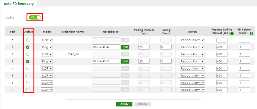
Auto PD Recovery (LLDP Mode)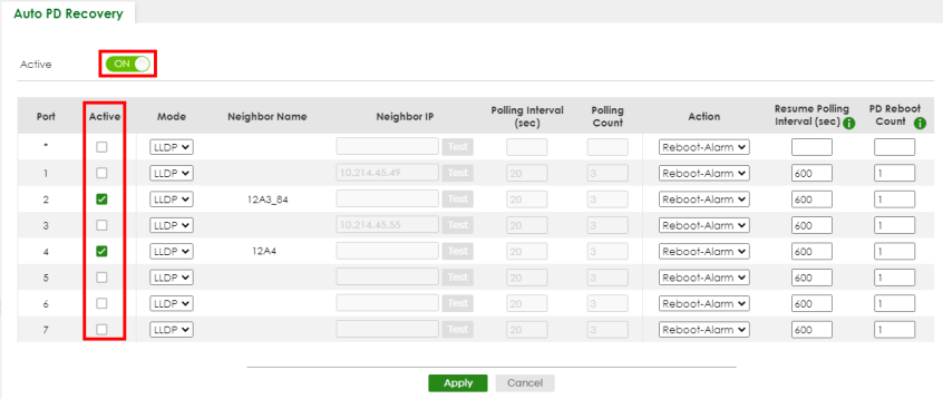
2 Select the desired ports in the Active column.
3 Select the Mode.
When you select Ping, the connected PD’s IPv4 or IPv6 address to which the Switch sends ping requests will display automatically if the PD supports LLDP. If not, enter the IP address of the PDs in the Neighbor IP field.
The default setting for Polling Interval (sec) (20 secs) and Polling Count (3 times) will cause the Switch to ping the PD status every 20 seconds. If there is no ping reply from the PD, Polling Count starts to count from 1. Once Polling Count reaches 3, the Switch will cause a Reboot-Alarm on the PD as selected in Action.
When you select LLDP, the Switch monitors the PD status by checking incoming LLDP packets every 30 seconds from the PD (default value of transmit interval for LLDP feature).
Likewise, the Switch sends out LLDP packets to the PD every 30 seconds to update the MONITOR > Neighbor > Neighbor screen.
Once the LLDP table’s counter reaches the default 120 seconds, the Switch will cause a Reboot-Alarm on the PD as selected in Action.
4 After sending an SNMP trap and generating a log message, the connected PD will restart (the connecting port is detected as link-down).
When restarting, the PD entry disappears from the Switch’s LLDP table and the PD Health status LED will turn to yellow in the MONITOR > Neighbor > Neighbor screen.
After the PD is powered on, the Switch resumes detection of the PD status by performing ping requests or checking the LLDP table based on your value for Resume Polling Interval.
When the PD Reboot Count value is reached, the Switch will no longer perform the PD recovery process. The PD Health status LED will turn to red in the MONITOR > Neighbor > Neighbor screen.
5 Click Apply to save your changes back to the run-time memory.
6 Click the Save link in the upper right corner of the Web Configurator to save your configuration permanently.
In the event of a PD performing firmware upgrade, the PD may stop responding to ping or fail to provide LLDP packets for an extended period of time. When the Switch resets power to the PD before firmware upgrade is finished, it may permanently damage the PD or require a hard reset to recover it. It is strongly advised to disable the Switch's Auto PD Recovery function before upgrading the PD's firmware. This will prevent damage caused by a power cutoff.