Link Layer Discovery Protocol (LLDP)
LLDP Overview
The LLDP (Link Layer Discovery Protocol) is a layer 2 protocol. It allows a network device to advertise its identity and capabilities on the local network. It also allows the device to maintain and store information from adjacent devices which are directly connected to the network device. This helps an administrator discover network changes and perform necessary network reconfiguration and management. The device information is encapsulated in the LLDPDUs (LLDP data units) in the form of TLV (Type, Length, Value). Device information carried in the received LLDPDUs is stored in the standard MIB.
The Switch supports these basic management TLVs.
• End of LLDPDU (mandatory)
• Chassis ID (mandatory)
• Port ID (mandatory)
• Time to Live (mandatory)
• Port Description (optional)
• System Name (optional)
• System Description (optional)
• System Capabilities (optional)
• Management Address (optional)
The Switch also supports the IEEE 802.1 and IEEE 802.3 organizationally-specific TLVs.
IEEE 802.1 specific TLVs:
• Port VLAN ID TLV (optional)
• Port and Protocol VLAN ID TLV (optional)
IEEE 802.3 specific TLVs:
• MAC/PHY Configuration/Status TLV (optional)
• Power via MDI TLV (optional, For PoE models only)
• Link Aggregation TLV (optional)
• Maximum Frame Size TLV (optional)
The optional TLVs are inserted between the Time To Live TLV and the End of LLDPDU TLV.
The next figure demonstrates that the network devices Switches and Routers (S and R) transmit and receive device information through LLDPDU and the network manager can query the information using Simple Network Management Protocol (SNMP).
LLDP Overview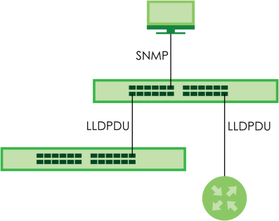
LLDP-MED Overview
LLDP-MED (Link Layer Discovery Protocol for Media Endpoint Devices) is an extension to the standard LLDP developed by the Telecommunications Industry Association (TIA) TR-41.4 subcommittee which defines the enhanced discovery capabilities, such as VoIP applications, to enable network administrators manage their network topology application more efficiently. Unlike the traditional LLDP, which has some limitations when handling multiple application devices, the LLDP-MED offers display of accurate physical topology, interoperability of devices, and easy trouble shooting for mis-configured IP addresses. There are three classes of endpoint devices that the LLDP-MED supports:
Class I: IP Communications Controllers or other communication related servers
Class II: Voice Gateways, Conference Bridges or Media Servers
Class III: IP-Phones, PC-based Softphones, End user Communication Appliances supporting IP Media
The following figure shows that with the LLDP-MED, network connectivity devices (NCD) like Switches and Routers will transmit LLDP TLV to endpoint device (ED) like IP Phone first (1), to get its device type and capabilities information, then it will receive that information in LLDP-MED TLV back from endpoint devices (2), after that the network connectivity devices will transmit LLDP-MED TLV (3) to provision the endpoint device to such that the endpoint device’s network policy and location identification information is updated. Since LLDPDU updates status and configuration information periodically, network managers may check the result of provision through remote status. The remote status is updated by receiving LLDP-MED TLVs from endpoint devices.
LLDP-MED Overview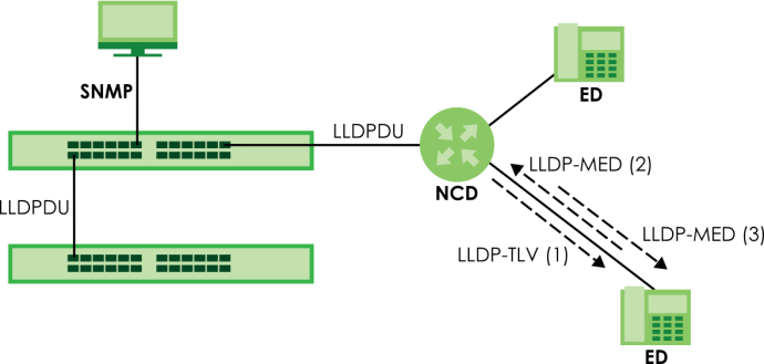
What You Can Do – LLDP
• Use the LLDP Remote Status screen (LLDP Remote Status) to view LLDP information from the neighboring devices.
• Use the Basic TLV Setting screen (Basic TLV Setting) to configure basic TLV settings on each port.
• Use the Org-specific TLV Setting screen (Org-specific TLV Setting) to configure organization-specific TLV settings on each port.
What You Can Do – LLDP MED
• Use the LLDP-MED Setup screen (LLDP-MED Setup) to configure LLDP-MED (Link Layer Discovery Protocol for Media Endpoint Devices) parameters.
• Use the LLDP-MED Network Policy screen (LLDP-MED Network Policy) to configure LLDP-MED (Link Layer Discovery Protocol for Media Endpoint Devices) network policy parameters.
• Use the LLDP-MED Location screen (LLDP-MED Location) to configure LLDP-MED (Link Layer Discovery Protocol for Media Endpoint Devices) location parameters.
LLDP Local Status
This screen displays a summary of LLDP status on this Switch. Click PORT > LLDP > LLDP > LLDP Local Status to display the screen as shown next.
PORT > LLDP > LLDP > LLDP Local Status (Standalone Mode)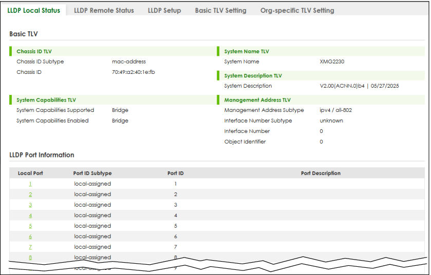
The following table describes the labels in this screen.
label | description |
|---|---|
Basic TLV | |
Chassis ID TLV | This displays the chassis ID of the local Switch, that is the Switch you are configuring. The chassis ID is identified by the chassis ID subtype. • Chassis ID Subtype – This displays how the chassis of the Switch is identified. • Chassis ID – This displays the chassis ID of the local Switch. |
System Name TLV | System Name – This shows the host name of the Switch. |
System Description TLV | System Description – This shows the firmware version of the Switch. |
System Capabilities TLV | This shows the System Capabilities enabled and supported on the local Switch. • System Capabilities Supported – Bridge • System Capabilities Enabled – Bridge |
Management Address TLV | The Management Address TLV identifies an address associated with the local LLDP agent that may be used to reach higher layer entities to assist discovery by network management. The TLV may also include the system interface number and an object identifier (OID) that are associated with this management address. This field displays the Management Address settings on the specified ports. • Management Address Subtype – ipv4 or all-802 • Interface Number Subtype – unknown • Interface Number – 0 (not supported) • Object Identifier – 0 (not supported) |
LLDP Port Information This displays the local port information. | |
Local Port | This displays the number of the Switch port which receives the LLDPDU from the remote device. Click a port number to view the detailed LLDP status on this port in the LLDP Local Port Status Details screen. |
Port ID Subtype | This indicates how the port ID field is identified. |
Port ID | This is an alpha-numeric string that contains the specific identifier for the port from which this LLDPDU was transmitted. |
Port Description | This shows the port description that the Switch will advertise from this port. |
LLDP Local Port Status Details
This screen displays detailed LLDP status for each port on this Switch. Click PORT > LLDP > LLDP > LLDP Local Status and then, click a port number, for example 1 in the local port column to display the screen as shown next.
PORT > LLDP > LLDP > LLDP Local Status > LLDP Local Port Status Detail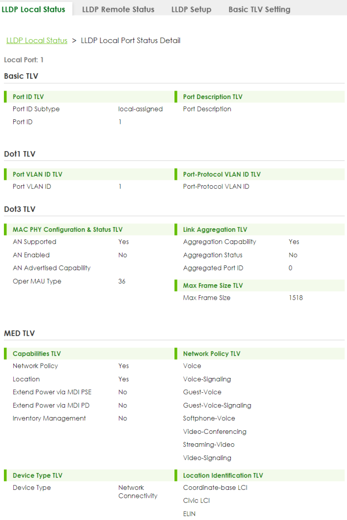
The following table describes the labels in this screen.
label | description |
|---|---|
Local Port | This displays the number of the Switch’s port. |
Basic TLV These are the Basic TLV flags | |
Port ID TLV | The port ID TLV identifies the specific port that transmitted the LLDP frame. • Port ID Subtype – This shows how the port is identified. • Port ID – This is the ID of the port. |
Port Description TLV | Port Description – This displays the local port description. |
Dot1 TLV | |
Port VLAN ID TLV | Port VLAN ID – This displays the VLAN ID sent by the IEEE 802.1 Port VLAN ID TLV. |
Port-Protocol VLAN ID TLV | Port-Protocol VLAN ID – This displays the IEEE 802.1 Port Protocol VLAN ID TLVs, which indicates whether the VLAN is enabled and supported. |
Dot3 TLV | |
MAC PHY Configuration & Status TLV | The MAC/PHY Configuration/Status TLV advertises the bit-rate and duplex capability of the sending 802.3 node. It also advertises the current duplex and bit-rating of the sending node. Lastly, it advertises whether these setting were the result of auto-negotiation during link initiation or manual override. • AN Supported – Displays if the port supports or does not support auto-negotiation. • AN Enabled – The current auto-negotiation status of the port. • AN Advertised Capability – The auto-negotiation capabilities of the port. • Oper MAU Type – The current Medium Attachment Unit (MAU) type of the port. |
Link Aggregation TLV | The Link Aggregation TLV indicates whether the link is capable of being aggregated, whether the link is currently in an aggregation, and if in an aggregation, the port identification of the aggregation. • Aggregation Capability – The current aggregation capability of the port. • Aggregation Status – The current aggregation status of the port. • Aggregation Port ID – The aggregation ID of the current port. |
Max Frame Size TLV | Max Frame Size – This displays the maximum supported frame size in octets. |
MED TLV LLDP Media Endpoint Discovery (MED) is an extension of LLDP that provides additional capabilities to support media endpoint devices. MED enables advertisement and discovery of network policies, device location discovery to allow creation of location databases, and information for troubleshooting. | |
Capabilities TLV | This field displays which LLDP-MED TLV are capable to transmit on the Switch. • Network Policy • Location • Extend Power via MDI PSE • Extend Power via MDI PD • Inventory Management |
Network Policy TLV | This displays a network policy for the specified application. • Voice • Voice-Signaling • Guest-Voice • Guest-Voice-Signaling • Softphone-Voice • Video-Conferencing • Streaming-Video • Video-Signaling |
Device Type TLV | Device Type – This is the LLDP-MED device class. The Zyxel Switch device type is: • Network Connectivity |
Location Identification TLV | This shows the location information of a caller by its ELIN (Emergency Location Identifier Number) or the IETF Geopriv Civic Address based Location Configuration Information (Civic Address LCI). • Coordinate-based LCI – Latitude, longitude and altitude coordinates of the location Configuration Information (LCI) • Civic LCI – IETF Geopriv Civic Address based Location Configuration Information • ELIN – (Emergency Location Identifier Number) |
LLDP Remote Status
This screen displays a summary of LLDP status for each LLDP connection to a neighboring Switch. Click PORT > LLDP > LLDP > LLDP Remote Status to display the screen as shown next.
PORT > LLDP > LLDP > LLDP Remote Status (Standalone Mode)
The following table describes the labels in this screen.
label | description |
|---|---|
Index | The index number shows the number of remote devices that are connected to the Switch. Click on an index number to view the detailed LLDP status for this remote device in the LLDP Remote Port Status Details screen. |
Local Port | This is the number of the Switch’s port that received LLDPDU from the remote device. |
Chassis ID | This displays the chassis ID of the remote device associated with the transmitting LLDP agent. The chassis ID is identified by the chassis ID subtype. For example, the MAC address of the remote device. |
Port ID | This is an alpha-numeric string that contains the specific identifier for the port from which this LLDPDU was transmitted. The port ID is identified by the port ID subtype. |
Port Description | This displays a description for the port from which this LLDPDU was transmitted. |
System Name | This displays the system name of the remote device. |
Management Address | This displays the management address of the remote device. It could be the MAC address or IP address. |
LLDP Remote Port Status Details
This screen displays detailed LLDP status of the remote device connected to the Switch. Click PORT > LLDP > LLDP > LLDP Remote Status and then click an index number, for example 1, in the Index column in the LLDP Remote Status screen to display the screen as shown next.
PORT > LLDP > LLDP > LLDP Remote Status > LLDP Remote Port Status Details (Basic TLV)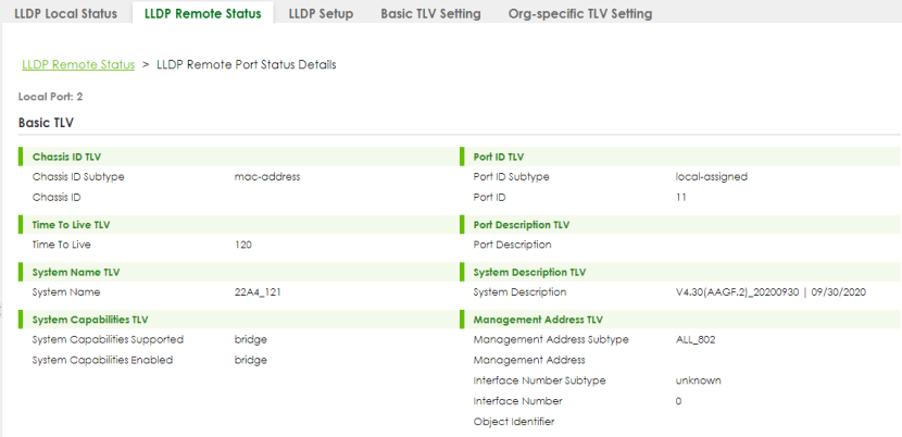
The following table describes the labels in Basic TLV part of the screen.
label | description |
|---|---|
Local Port | This displays the number of the Switch’s port to which the remote device is connected. |
Basic TLV | |
Chassis ID TLV | • Chassis ID Subtype – This displays how the chassis of the remote device is identified. • Chassis ID – This displays the chassis ID of the remote device. The chassis ID is identified by the chassis ID subtype. |
Port ID TLV | • Port ID Subtype – This displays how the port of the remote device is identified. • Port ID – This displays the port ID of the remote device. The port ID is identified by the port ID subtype. |
Time To Live TLV | Time To Live – This displays the time-to-live (TTL) multiplier of LLDP frames. The device information on the neighboring devices ages out and is discarded when its corresponding TTL expires. The TTL value is to multiply the TTL multiplier by the LLDP frames transmitting interval. |
Port Description TLV | Port Description – This displays the remote port description. |
System Name TLV | System Name – This displays the system name of the remote device. |
System Description TLV | System Description – This displays the system description of the remote device. |
System Capabilities TLV | This displays whether the system capabilities are enabled and supported on the remote device. • System Capabilities Supported • System Capabilities Enabled |
Management Address TLV | This displays the management address (IPv4 and IPv6) of the remote device. • Management Address Subtype • Management Address • Interface Number Subtype • Interface Number • Object Identifier |
PORT > LLDP > LLDP > LLDP Remote Status > LLDP Remote Port Status Details (Dot1 and Dot3 TLV)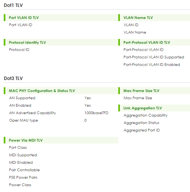
The following table describes the labels in the Dot1 and Dot3 parts of the screen.
label | description |
|---|---|
Dot1 TLV | |
Port VLAN ID TLV | Port VLAN ID – This displays the VLAN ID of this port on the remote device. |
Vlan Name TLV | This shows the VLAN ID and name for remote device port. • VLAN ID • VLAN Name |
Protocol Identity TLV | Protocol ID – The Protocol Identity TLV allows the Switch to advertise the particular protocols that are accessible through its port. |
Port-Protocol VLAN ID TLV | This displays the IEEE 802.1 Port Protocol VLAN ID TLV, which indicates whether the VLAN ID and whether it is enabled and supported on the port of remote Switch which sent the LLDPDU. • Port-Protocol VLAN ID • Port-Protocol VLAN ID Supported • Port-Protocol VLAN ID Enabled |
Dot3 TLV | |
MAC PHY Configuration & Status TLV | The MAC/PHY Configuration/Status TLV advertises the bit-rate and duplex capability of the sending 802.3 node. It also advertises the current duplex and bit-rating of the sending node. Lastly, it advertises whether these setting were the result of auto-negotiation during link initiation or manual override. • AN Supported – Displays if the port supports or does not support auto-negotiation. • AN Enabled – The current auto-negotiation status of the port. • AN Advertised Capability – The auto-negotiation capabilities of the port. • Oper MAU Type – The current Medium Attachment Unit (MAU) type of the port. |
Max Frame Size TLV | Max Frame Size – This displays the maximum supported frame size in octets. |
Link Aggregation TLV | The Link Aggregation TLV indicates whether the link is capable of being aggregated, whether the link is currently in an aggregation, and if in an aggregation, the port identification of the aggregation. • Aggregation Capability – The current aggregation capability of the port. • Aggregation Status – The current aggregation status of the port. • Aggregated Port ID – The aggregation ID of the current port. |
Power Via MDI TLV | The Power Via MDI TLV allows network management to advertise and discover the MDI power support capabilities of the sending port on the remote device. • Port Class • MDI Supported • MDI Enabled • Pair Controllable • PSE Power Pairs • Power Class |
PORT > LLDP > LLDP > LLDP Remote Status > LLDP Remote Port Status Details (MED TLV)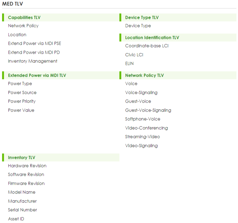
The following table describes the labels in the MED TLV part of the screen.
label | description |
|---|---|
MED TLV LLDP Media Endpoint Discovery (MED) is an extension of LLDP that provides additional capabilities to support media endpoint devices. MED enables advertisement and discovery of network policies, device location discovery to allow creation of location databases, and information for troubleshooting. | |
Capabilities TLV | This displays the MED capabilities the remote port supports. • Network Policy • Location • Extend Power via MDI PSE • Extend Power via MDI PD • Inventory Management |
Device Type TLV | LLDP-MED endpoint device classes: • Endpoint Class I • Endpoint Class II • Endpoint Class III • Network Connectivity |
Location Identification TLV | This shows the location information of a caller by its: • Coordinate-base LCI – Latitude and longitude coordinates of the Location Configuration Information (LCI) • Civic LCI – IETF Geopriv Civic Address based Location Configuration Information • ELIN – (Emergency Location Identifier Number) |
Extended Power via MDI TLV | Extended Power Via MDI Discovery enables detailed power information to be advertised by Media Endpoints, such as IP phones and Network Connectivity Devices such as the Switch. • Power Type – Whether it is currently operating from primary power or is on backup power (backup power may indicate to the Endpoint Device that it should move to a power conservation mode). • Power Source – Whether or not the Endpoint is currently operating from an external power source. • Power Priority – The Endpoint Device’s power priority (which the Network Connectivity Device may use to prioritize which devices will remain in service during power shortages). • Power Value – Power requirement, in fractions of Watts, in current configuration. |
Network Policy TLV | This displays a network policy for the specified application. • Voice • Voice-Signaling • Guest-Voice • Guest-Voice-Signaling • Softphone-Voice • Video-Conferencing • Streaming-Video • Video-Signaling |
Inventory TLV | The majority of IP Phones lack support of management protocols such as SNMP, so LLDP-MED inventory TLVs are used to provide their inventory information to the Network Connectivity Devices such as the Switch. The Inventory TLV may contain the following information. • Hardware Revision • Software Revision • Firmware Revision • Model Name • Manufacturer • Serial Number • Asset ID |
LLDP Setup
Use this screen to configure global LLDP settings on the Switch. Click PORT > LLDP > LLDP > LLDP Setup to display the screen as shown next.
PORT > LLDP > LLDP > LLDP Setup (Standalone Mode)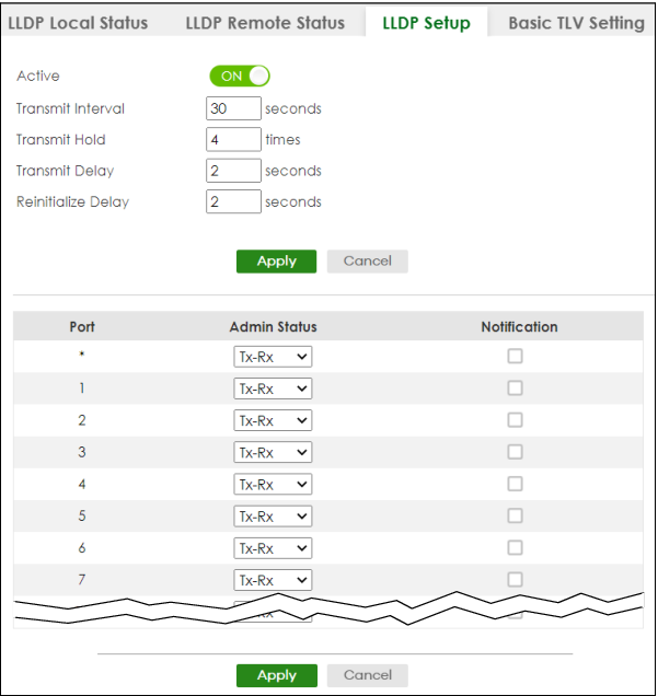
The following table describes the labels in this screen.
label | description |
|---|---|
Active | Select to enable LLDP on the Switch. It is enabled by default. |
Transmit Interval | Enter how many seconds the Switch waits before sending LLDP packets. |
Transmit Hold | Enter the time-to-live (TTL) multiplier of LLDP frames. The device information on the neighboring devices ages out and is discarded when its corresponding TTL expires. The TTL value is to multiply the TTL multiplier by the LLDP packets transmitting interval. |
Transmit Delay | Enter the delay (in seconds) between successive LLDPDU transmissions initiated by value or status changes in the Switch MIB. |
Reinitialize Delay | Enter the number of seconds for LLDP to wait before initializing on a port. |
Apply | Click Apply to save your changes to the Switch’s run-time memory. The Switch loses these changes if it is turned off or loses power, so use the Save link on the top navigation panel to save your changes to the non-volatile memory when you are done configuring. |
Cancel | Click Cancel to begin configuring this screen afresh. |
Port | This displays the Switch’s port number. * means all ports. |
* | Use this row to make the setting the same for all ports. Use this row first and then make adjustments to each port if necessary. Changes in this row are copied to all the ports as soon as you make them. |
Admin Status | Select whether LLDP transmission and/or reception is allowed on this port. • Disable – not allowed • Tx-Only – transmit only • Rx-Only – receive only • Tx-Rx – transmit and receive |
Notification | Select whether LLDP notification is enabled on this port. |
Apply | Click Apply to save your changes to the Switch’s run-time memory. The Switch loses these changes if it is turned off or loses power, so use the Save link on the top navigation panel to save your changes to the non-volatile memory when you are done configuring. |
Cancel | Click Cancel to begin configuring this screen afresh. |
Basic TLV Setting
Use this screen to configure Basic TLV settings. Click PORT > LLDP > LLDP > Basic TLV Setting to display the screen as shown next.
PORT > LLDP > LLDP > Basic TLV Setting (Standalone Mode)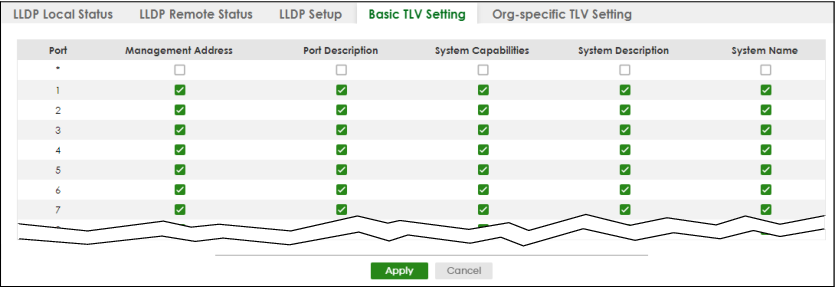
The following table describes the labels in this screen.
label | description |
|---|---|
Port | This displays the Switch’s port number. |
* | Use this row to make the setting the same for all ports. Use this row first and then make adjustments to each port if necessary. Changes in this row are copied to all the ports as soon as you make them. |
Management Address | Select the checkboxes to enable or disable the sending of Management Address TLVs on the ports. |
Port Description | Select the checkboxes to enable or disable the sending of Port Description TLVs on the ports. |
System Capabilities | Select the checkboxes to enable or to disable the sending of System Capabilities TLVs on the ports. |
System Description | Select the checkboxes to enable or to disable the sending of System Description TLVs on the ports. |
System Name | Select the checkboxes to enable or to disable the sending of System Name TLVs on the ports. |
Apply | Click Apply to save your changes to the Switch’s run-time memory. The Switch loses these changes if it is turned off or loses power, so use the Save link on the top navigation panel to save your changes to the non-volatile memory when you are done configuring. |
Cancel | Click Cancel to begin configuring this screen afresh. |
Org-specific TLV Setting
Use this screen to configure organization-specific TLV settings. Click PORT > LLDP > LLDP > Org-specific TLV Setting to display the screen as shown next.
PORT > LLDP > LLDP > Org-specific TLV Setting (Standalone Mode)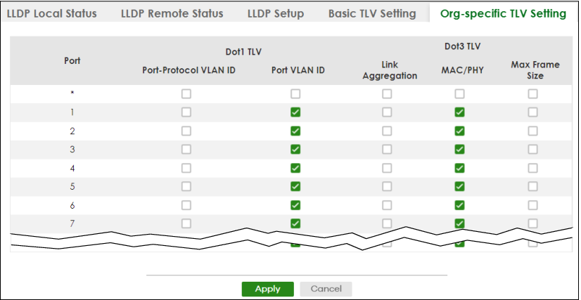
The following table describes the labels in this screen.
label | description |
|---|---|
Port | This displays the Switch’s port number. |
* | Use this row to make the setting the same for all ports. Use this row first and then make adjustments to each port if necessary. Changes in this row are copied to all the ports as soon as you make them. |
Dot1 TLV | |
Port-Protocol VLAN ID | Select the checkboxes to enable or disable the sending of IEEE 802.1 Port and Protocol VLAN ID TLVs on the ports. |
Port VLAN ID | Select the checkboxes to enable or disable the sending of IEEE 802.1 Port VLAN ID TLVs on the ports. All checkboxes in this column are enabled by default. |
Dot3 TLV | |
Link Aggregation | Select the checkboxes to enable or disable the sending of IEEE 802.3 Link Aggregation TLVs on the ports. |
MAC/PHY | Select the checkboxes to enable or disable the sending of IEEE 802.3 MAC/PHY Configuration/Status TLVs on the ports. All checkboxes in this column are enabled by default. |
Max Frame Size | Select the checkboxes to enable or disable the sending of IEEE 802.3 Max Frame Size TLVs on the ports. |
Apply | Click Apply to save your changes to the Switch’s run-time memory. The Switch loses these changes if it is turned off or loses power, so use the Save link on the top navigation panel to save your changes to the non-volatile memory when you are done configuring. |
Cancel | Click Cancel to begin configuring this screen afresh. |
LLDP-MED Setup
Click PORT > LLDP > LLDP MED > LLDP-MED Setup to display the screen as shown next.
PORT > LLDP > LLDP MED > LLDP-MED Setup (Standalone Mode)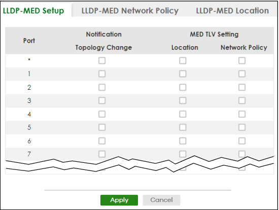
The following table describes the labels in this screen.
label | description |
|---|---|
Port | This displays the Switch’s port number. Select * to configure all ports simultaneously. |
* | Use this row to make the setting the same for all ports. Use this row first and then make adjustments to each port if necessary. Changes in this row are copied to all the ports as soon as you make them. |
Notification | |
Topology Change | Select to enable LLDP-MED topology change traps on this port. |
MED TLV Setting | |
Location | Select to enable transmitting LLDP-MED location TLV. |
Network Policy | Select to enable transmitting LLDP-MED Network Policy TLV. |
Apply | Click Apply to save the changes to the Switch’s run-time memory. The Switch loses these changes if it is turned off or loses power, so use the Save link on the top navigation panel to save your changes to the non-volatile memory when you are done configuring. |
Cancel | Click Cancel to begin configuring this screen afresh. |
LLDP-MED Network Policy
Click PORT > LLDP > LLDP MED > LLDP-MED Network Policy to display the screen as shown next.
PORT > LLDP > LLDP MED > LLDP-MED Network Policy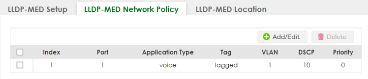
The following table describes the labels in this screen.
label | description |
|---|---|
Index | This field displays the of index number of the network policy. Click an index number to edit the rule. |
Port | This field displays the port number of the network policy. |
Application Type | This field displays the application type of the network policy. |
Tag | This field displays the Tag Status of the network policy. |
VLAN | This field displays the VLAN ID of the network policy. |
DSCP | This field displays the DSCP value of the network policy. |
Priority | This field displays the priority value of the network policy. |
Select an entry’s checkbox to select a specific entry. Otherwise, select the checkbox in the table heading row to select all entries. | |
Add/Edit | Click Add/Edit to add a new schedule rule or edit a selected one. |
Delete | Select the rules that you want to remove, then click Delete. |
Add/Edit LLDP-MED Network Policy
To access this screen, click the Add/Edit button or select an entry from the list and click the Add/Edit button.
PORT > LLDP > LLDP MED > LLDP-MED Network Policy > Add/Edit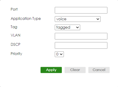
The following table describes the labels in this screen.
label | description |
|---|---|
Port | Enter the port number to set up the LLDP-MED network policy. You can enter multiple ports separated by (no space) comma (“,”) or hyphen (“-”) for a range. For example, enter “3-5” for ports 3, 4, and 5. Enter “3,5,7” for ports 3, 5, and 7. |
Application Type | Select the type of application used in the network policy. • voice • voice-signaling • guest-voice • guest-voice-signaling • softphone-voice • video-conferencing • streaming-video • video-signaling |
Tag | Select to tag or untag in the network policy. • tagged • untagged |
VLAN | Enter the VLAN ID number. It should be from 1 to 4094. For priority tagged frames, enter “0”. |
DSCP | Enter the DSCP value of the network policy. The value is defined from 0 through 63 with the 0 representing use of the default DSCP value. |
Priority | Enter the priority value for the network policy. |
Apply | Click Apply to save your changes to the Switch’s run-time memory. The Switch loses these changes if it is turned off or loses power, so use the Save link on the top navigation panel to save your changes to the non-volatile memory when you are done configuring. |
Clear | Click Clear to clear the fields to the factory defaults. |
Cancel | Click Cancel to not save the configuration you make and return to the last screen. |
LLDP-MED Location
Click PORT > LLDP > LLDP MED > LLDP-MED Location to display the screen as shown next.
PORT > LLDP > LLDP MED > LLDP-MED Location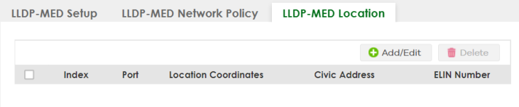
The following table describes the labels in this screen.
label | description |
|---|---|
Index | This lists the index number of the location configuration. Click an index number to view or edit the location. |
Port | This lists the port number of the location configuration. |
Location Coordinates | This field displays the location configuration information based on geographical coordinates that includes longitude, latitude, altitude and datum. |
Civic Address | This field displays the Civic Address for the remote device using information such as Country, State, County, City, Street, Number, ZIP code and additional information. |
ELIN Number | This field shows the Emergency Location Identification Number (ELIN), which is used to identify endpoint devices when they issue emergency call services. The valid length is form 10 to 25 characters. |
Select an entry’s checkbox to select a specific entry. Otherwise, select the checkbox in the table heading row to select all entries. | |
Add/Edit | Click Add/Edit to add a new location or edit a selected one. |
Delete | Select the locations that you want to remove, then click Delete. |
Add/Edit LLDP-MED Location
To access this screen, click the Add/Edit button or select an entry from the list and click the Add/Edit button.
PORT > LLDP > LLDP MED > LLDP-MED Location > Add/Edit (Standalone Mode)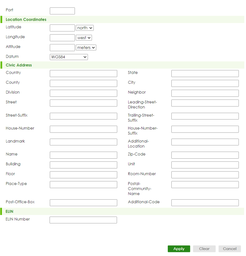
The following table describes the labels in this screen.
label | description |
|---|---|
Port | Enter the port number you want to set up the location within the LLDP-MED network. |
Location Coordinates The LLDP-MED uses geographical coordinates and Civic Address to set the location information of the remote device. Geographical based coordinates includes latitude, longitude, altitude and datum. Civic Address includes Country, State, County, City, Street and other related information. | |
Latitude | Enter the latitude information. The value should be from 0º to 90º. • north • south |
Longitude | Enter the longitude information. The value should be from 0º to 180º. • west • east |
Altitude | Enter the altitude information. The value should be from –2097151 to 2097151 in meters or in floors. • meters • floor |
Datum | Select the appropriate geodetic datum used by GPS. • WGS84 • NAD83-NAVD88 • NAD83-MLLW |
Civic Address | Enter the Civic Address by providing information such as Country, State, County, City, Street, Number, ZIP code and other additional information. Enter at least 2 fields in this configuration including the Country. The valid length of the Country field is 2 characters and all other fields are up to 32 characters. • Country • State • County • City • Division • Neighbor • Street • Leading-Street-Direction • Street-Suffix • Trailing-Street-Suffix • House-Number • House-Number-Suffix • Landmark • Additional-Location • Name • Zip-Code • Building • Unit • Floor • Room-Number • Place-Type • Postal-Community-Name • Post-Office-Box • Additional-Code |
ELIN Number | Enter a numerical digit string, corresponding to the ELIN identifier which is used during emergency call setup to a traditional CAMA or ISDN trunk-based PSAP. The valid length is from 10 to 25 characters. |
Apply | Click Apply to save your changes to the Switch’s run-time memory. The Switch loses these changes if it is turned off or loses power, so use the Save link on the top navigation panel to save your changes to the non-volatile memory when you are done configuring. |
Clear | Click Clear to clear the fields to the factory defaults. |
Cancel | Click Cancel to not save the configuration you make and return to the last screen. |