Multicast
Multicast Overview
This chapter shows you how to configure various multicast features.
Traditionally, IP packets are transmitted in one of either two ways – Unicast (one sender to one recipient) or Broadcast (one sender to everybody on the network). Multicast delivers IP packets to just a group of hosts on the network.
IGMP (Internet Group Management Protocol) is a network-layer protocol used to establish membership in a multicast group – it is not used to carry user data. Refer to RFC 1112, RFC 2236 and RFC 3376 for information on IGMP versions 1, 2 and 3 respectively.
The Multicast Listener Discovery (MLD) protocol (defined in RFC 2710) is derived from IPv4's Internet Group Management Protocol version 2 (IGMPv2). MLD uses ICMPv6 message types, rather than IGMP message types. MLDv1 is similar to IGMPv2 and MLDv2 is similar to IGMPv3. MLD allows an IPv6 switch or router to discover the presence of MLD listeners who wish to receive multicast packets and the IP addresses of multicast groups the hosts want to join on its network.
MLD snooping and MLD proxy are analogous to IGMP snooping and IGMP proxy in IPv4. MLD filtering controls which multicast groups a port can join.
What You Can Do – IPv4 Multicast
• Use the IPv4 Multicast Status screen (IPv4 Multicast Status) to view IPv4 multicast group information.
• Use the IGMP Snooping screen (IGMP Snooping) to enable IGMP snooping to forward group multicast traffic only to ports that are members of that group.
• Use the IGMP Filtering Profile (IGMP Filtering Profile) to specify a range of multicast groups that clients connected to the Switch are able to join.
What You Can Do – IPv6 Multicast
• Use the IPv6 Multicast Status screen (IPv6 Multicast Status) to view IPv6 multicast group information.
• Use the MLD Snooping-proxy screen (MLD Snooping-proxy) to enable the upstream port to report group changes to a connected multicast router and forward MLD messages to other upstream ports.
• Use the MLD Snooping-proxy VLAN screen (MLD Snooping-proxy VLAN) to enable and configure MLD snooping-proxy settings on the VLANs you specified.
• Use the MLD Snooping-proxy Port Role Setting screen (MLD Snooping-proxy Port Role Setting) to assign MLD snooping-proxy port roles and configure Leave settings for each port.
• Use the MLD Snooping-proxy Filtering screen (MLD Snooping-proxy Filtering) to enable and configure MLD snooping-proxy filtering.
• Use the MLD Snooping-proxy Filtering Profile screen (MLD Snooping-proxy Filtering Profile) to create/edit MLD snooping-proxy filtering profiles.
What You Can Do – MVR
• Use the MVR screen (MVR Configuration) to create multicast VLANs and select the receiver ports and a source port for each multicast VLAN.
What You Need to Know
Read on for concepts on Multicasting that can help you configure the screens in this chapter.
IP Multicast Addresses
In IPv4, a multicast address allows a device to send packets to a specific group of hosts (multicast group) in a different subnetwork. A multicast IP address represents a traffic receiving group, not individual receiving devices. IP addresses in the Class D range (224.0.0.0 to 239.255.255.255) are used for IP multicasting. Certain IP multicast numbers are reserved by IANA for special purposes (see the IANA website for more information).
In IPv6, multicast addresses provide the same functionality as IPv4 broadcast addresses. Broadcasting is not supported in IPv6. A multicast address allows a host to send packets to all hosts in a multicast group. Multicast scope allows you to determine the size of the multicast group. A multicast address has a predefined prefix of ff00::/8.
IGMP Filtering
With the IGMP filtering feature, you can control which IGMP groups a subscriber on a port can join. This allows you to control the distribution of multicast services (such as content information distribution) based on service plans and types of subscription.
You can set the Switch to filter the multicast group join reports on a per-port basis by configuring an IGMP filtering profile and associating the profile to a port.
IGMP Snooping
A Switch can passively snoop on IGMP packets transferred between IP multicast routers or switches and IP multicast hosts to learn the IP multicast group membership. It checks IGMP packets passing through it, picks out the group registration information, and configures multicasting accordingly. IGMP snooping allows the Switch to learn multicast groups without you having to manually configure them.
The Switch forwards multicast traffic destined for multicast groups (that it has learned from IGMP snooping or that you have manually configured) to ports that are members of that group. IGMP snooping generates no additional network traffic, allowing you to significantly reduce multicast traffic passing through your Switch.
IGMP Snooping and VLANs
The Switch can perform IGMP snooping on up to 16 VLANs. You can configure the Switch to automatically learn multicast group membership of any VLANs. The Switch then performs IGMP snooping on the first 16 VLANs that send IGMP packets. This is referred to as auto mode. Alternatively, you can specify the VLANs that IGMP snooping should be performed on. This is referred to as fixed mode. In fixed mode the Switch does not learn multicast group membership of any VLANs other than those explicitly added as an IGMP snooping VLAN.
MLD Snooping-proxy
MLD snooping-proxy is a Zyxel-proprietary feature. IPv6 MLD proxy allows only one upstream interface on a switch, while MLD snooping-proxy supports more than one upstream port on a switch. The upstream port in MLD snooping-proxy can report group changes to a connected multicast router and forward MLD messages to other upstream ports. This helps especially when you want to have a network that uses STP to provide backup links between switches and also performs MLD snooping and proxy functions. MLD snooping-proxy, like MLD proxy, can minimize MLD control messages and allow better network performance.
In MLD snooping-proxy, if one upstream port is learned through snooping, all other upstream ports on the same device will be added to the same group. If one upstream port requests to leave a group, all other upstream ports on the same device will also be removed from the group.
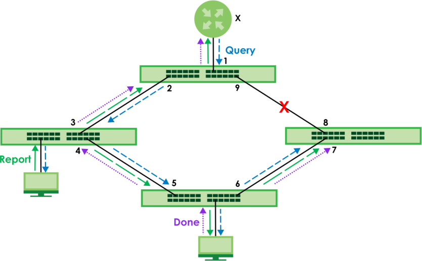
In the following MLD snooping-proxy example, all connected upstream ports (1 – 7) are treated as one interface. The connection between ports 8 and 9 is blocked by STP to break the loop. If there is one Query from a router (X) or MLD Done or Report message from any upstream port, it will be broadcast to all connected upstream ports.
MLD Messages
A multicast router or switch periodically sends general queries to MLD hosts to update the multicast forwarding table. When an MLD host wants to join a multicast group, it sends an MLD Report message for that address.
An MLD Done message is similar to an IGMP Leave message. When an MLD host wants to leave a multicast group, it can send a Done message to the router or switch. If the leave mode is not set to Immediate, the router or switch sends a group-specific query to the port on which the Done message is received to determine if other devices connected to this port should remain in the group.
MVR Overview
Multicast VLAN Registration (MVR) is designed for applications (such as Media-on-Demand (MoD)) that use multicast traffic across an Ethernet ring-based service provider network.
MVR allows one single multicast VLAN to be shared among different subscriber VLANs on the network. While isolated in different subscriber VLANs, connected devices can subscribe to and unsubscribe from the multicast stream in the multicast VLAN. This improves bandwidth utilization with reduced multicast traffic in the subscriber VLANs and simplifies multicast group management.
MVR only responds to IGMP join and leave control messages from multicast groups that are configured under MVR. Join and leave reports from other multicast groups are managed by IGMP snooping.
The following figure shows a network example. The subscriber VLAN (1, 2 and 3) information is hidden from the streaming media server (S). In addition, the multicast VLAN (MVLAN) information is only visible to the Switch and S.
MVR Network Example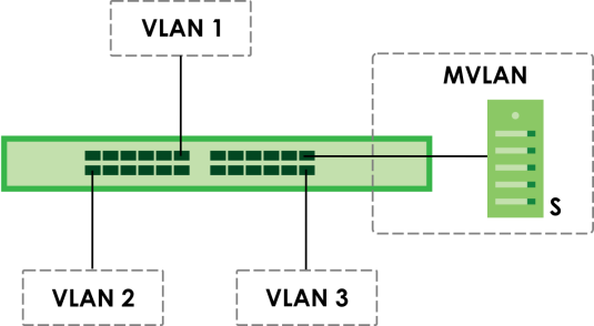
Types of MVR Ports
In MVR, a source port is a port on the Switch that can send and receive multicast traffic in a multicast VLAN while a receiver port can only receive multicast traffic. Once configured, the Switch maintains a forwarding table that matches the multicast stream to the associated multicast group.
MVR Modes
You can set your Switch to operate in either dynamic or compatible mode.
In dynamic mode, the Switch sends IGMP leave and join reports to the other multicast devices (such as multicast routers or servers) in the multicast VLAN. This allows the multicast devices to update the multicast forwarding table to forward or not forward multicast traffic to the receiver ports.
In compatible mode, the Switch does not send any IGMP reports. In this case, you must manually configure the forwarding settings on the multicast devices in the multicast VLAN.
How MVR Works
The following figure shows a multicast television example where a subscriber device (such as a computer) in VLAN 1 receives multicast traffic from the streaming media server (S), through the Switch. Multiple subscriber devices can connect through a port configured as the receiver on the Switch.
When the subscriber selects a television channel, computer A sends an IGMP report to the Switch to join the appropriate multicast group. If the IGMP report matches one of the configured MVR multicast group addresses on the Switch, an entry is created in the forwarding table on the Switch. This maps the subscriber VLAN to the list of forwarding destinations for the specified multicast traffic.
When the subscriber changes the channel or turns off the computer, an IGMP leave message is sent to the Switch to leave the multicast group. The Switch sends a query to VLAN 1 on the receiver port (in this case, an uplink port on the Switch). If there is another subscriber device connected to this port in the same subscriber VLAN, the receiving port will still be on the list of forwarding destination for the multicast traffic. Otherwise, the Switch removes the receiver port from the forwarding table.
MVR Multicast Television Example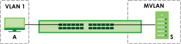
IPv4 Multicast Status
Click SWITCHING > Multicast > IPv4 Multicast > IPv4 Multicast Status to display the screen as shown. This screen shows the IPv4 multicast group information. See Multicast Overview for more information on multicasting.
SWITCHING > Multicast > IPv4 Multicast > IPv4 Multicast Status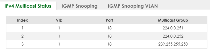
The following table describes the labels in this screen.
label | description |
|---|---|
Index | This is the index number of the entry. |
VID | This field displays the multicast VLAN ID. |
Port | This field displays the port number that belongs to the multicast group. |
Multicast Group | This field displays IP multicast group addresses. |
IGMP Snooping
Click SWITCHING > Multicast > IPv4 Multicast > IGMP Snooping to display the screen as shown. See Multicast Overview for more information on multicasting.
SWITCHING > Multicast > IPv4 Multicast > IGMP Snooping (Standalone Mode)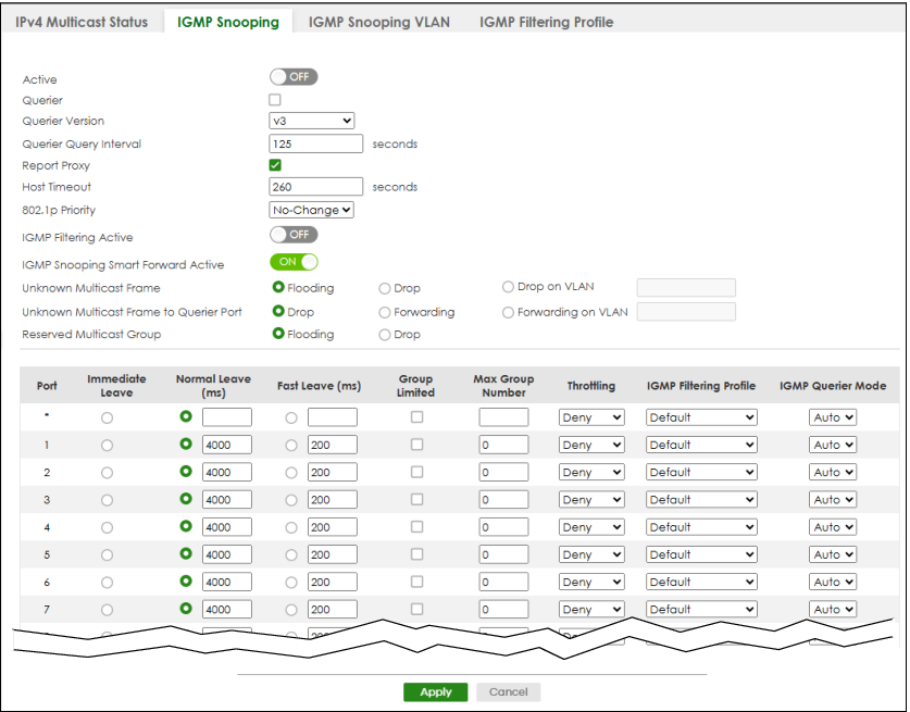
The following table describes the labels in this screen.
label | description |
|---|---|
Active | Enable the switch button to enable IGMP Snooping to forward group multicast traffic only to ports that are members of that group. |
Querier | Select this to allow the Switch to send IGMP General Query messages to the VLANs with the multicast hosts attached. |
Querier Version | IGMP snooping query works only when both host and Switch support the same IGMP version. Select v2 to allow the Switch to send IGMPv2 queries only. Select v3 to allow the Switch to send IGMPv3 queries only. |
Querier Query Interval | Enter the period in seconds between each IGMP snooping query (1–65535). |
Report Proxy | Select this to allow the Switch to act as the IGMP report proxy and leave proxy. It will report group changes to a connected multicast router. The Switch not only checks IGMP packets between multicast routers or switches and multicast hosts to learn the multicast group membership, but also replaces the source MAC address in an IGMP v1/v2 report with its own MAC address before forwarding to the multicast router or switch. When the Switch receives more than one IGMP v1/v2 join report that requests to join the same multicast group, it only sends a new join report with its MAC address. This helps reduce the number of multicast join reports passed to the multicast router or switch. The Switch sends a leave message with its MAC address to the multicast router or switch only when it receives the leave message from the last host in a multicast group. |
Host Timeout | Specify the time (from 1 to 16711450) in seconds that elapses before the Switch removes an IGMP group membership entry if it does not receive report messages from the port. |
802.1p Priority | Select a priority level (0 – 7) to which the Switch changes the priority in outgoing IGMP control packets. Otherwise, select No-Change to not replace the priority. |
IGMP Filtering Active | Enable the switch button to enable IGMP filtering to control which IGMP groups a subscriber on a port can join. If you enable IGMP filtering, you must create and assign IGMP filtering profiles for the ports that you want to allow to join multicast groups. |
IGMP Snooping Smart Forward Active | Enable the switch button to enable sending of multicast frame to querier port and IGMP subscriber groups. Otherwise, the querier port forwards the frames only when it receives a join report and it belongs to the IGMP group. |
Unknown Multicast Frame | Specify the action to perform when the Switch receives an unknown multicast frame. • Select Flooding to send the frames to all ports. • Select Drop to discard the frames. • Select Drop on VLAN and enter the VLAN ID numbers to discard the frames on the specified VLANs. Use a dash to specify consecutive VLANs and a comma (no spaces) to specify non-consecutive VLANs. For example, 51–53 includes 51, 52 and 53, but 51,53 does not include 52. |
Unknown Multicast Frame to Querier Port | Specify the action to perform when Unknown Multicast Frame is set to Drop. • Select Drop to discard the frames. • Select Forwarding to send the frames to all querier ports. • Select Forwarding on VLAN and enter the VLAN ID numbers to send the frames to the ports which are used as an IGMP query port on the specified VLANs. Use a dash to specify consecutive VLANs and a comma (no spaces) to specify non-consecutive VLANs. For example, 51–53 includes 51, 52 and 53, but 51,53 does not include 52. |
Reserved Multicast Group | The IP address range of 224.0.0.0 to 224.0.0.255 are reserved for multicasting on the local network only. For example, 224.0.0.1 is for all hosts on a local network segment and 224.0.0.9 is used to send RIP routing information to all RIP v2 routers on the same network segment. A multicast router will not forward a packet with the destination IP address within this range to other networks. See the IANA web site for more information. The layer-2 multicast MAC addresses used by Cisco layer-2 protocols, 01:00:0C:CC:CC:CC and 01:00:0C:CC:CC:CD, are also included in this group. Specify the action to perform when the Switch receives a frame with a reserved multicast address. • Select Flooding to send the frames to all ports. • Select Drop to discard the frames. |
Use this section to configure IGMP Snooping on each port. | |
Port | This field displays the port number. |
* | Settings in this row apply to all ports. Use this row only if you want to make some settings the same for all ports. Use this row first to set the common settings and then make adjustments on a port-by-port basis. Changes in this row are copied to all the ports as soon as you make them. |
Immediate Leave | Select this to set the Switch to remove this port from the multicast tree when an IGMP version 2 leave message is received on this port. Select this option if there is only one host connected to this port. |
Normal Leave (ms) | Enter an IGMP normal leave timeout value (from 200 to 6348800) in miliseconds. Select this option to have the Switch use this timeout to update the forwarding table for the port. In normal leave mode, when the Switch receives an IGMP leave message from a host on a port, it forwards the message to the multicast router. The multicast router then sends out an IGMP Group-Specific Query (GSQ) message to determine whether other hosts connected to the port should remain in the specific multicast group. The Switch forwards the query message to all hosts connected to the port and waits for IGMP reports from hosts to update the forwarding table. This defines how many seconds the Switch waits for an IGMP report before removing an IGMP snooping membership entry when an IGMP leave message is received on this port from a host. |
Fast Leave (ms) | Enter an IGMP fast leave timeout value (from 200 to 6348800) in miliseconds. Select this option to have the Switch use this timeout to update the forwarding table for the port. In fast leave mode, right after receiving an IGMP leave message from a host on a port, the Switch itself sends out an IGMP Group-Specific Query (GSQ) message to determine whether other hosts connected to the port should remain in the specific multicast group. This helps speed up the leave process. This defines how many seconds the Switch waits for an IGMP report before removing an IGMP snooping membership entry when an IGMP leave message is received on this port from a host. |
Group Limited | Select this option to limit the number of multicast groups this port is allowed to join. |
Max Group Number | Enter the number of multicast groups this port is allowed to join. Once a port is registered in the specified number of multicast groups, any new IGMP join report frames is dropped on this port. |
Throttling | IGMP throttling controls how the Switch deals with the IGMP reports when the maximum number of the IGMP groups a port can join is reached. Select Deny to drop any new IGMP join report received on this port until an existing multicast forwarding table entry is aged out. Select Replace to replace an existing entry in the multicast forwarding table with the new IGMP reports received on this port. |
IGMP Filtering Profile | Select the name of the IGMP filtering profile to use for this port. Otherwise, select Default to prohibit the port from joining any multicast group. You can create IGMP filtering profiles in the SWITCHING > Multicast > IPv4 Multicast > IGMP Filtering Profile screen. |
IGMP Querier Mode | The Switch treats an IGMP query port as being connected to an IGMP multicast router (or server). The Switch forwards IGMP join or leave packets to an IGMP query port. Select Auto to have the Switch use the port as an IGMP query port if the port receives IGMP query packets. Select Fixed to have the Switch always use the port as an IGMP query port. Select this when you connect an IGMP multicast server to the port. Select Edge to stop the Switch from using the port as an IGMP query port. The Switch will not keep any record of an IGMP router being connected to this port. The Switch does not forward IGMP join or leave packets to this port. |
Apply | Click Apply to save your changes to the Switch’s run-time memory. The Switch loses these changes if it is turned off or loses power, so use the Save link on the top navigation panel to save your changes to the non-volatile memory when you are done configuring. |
Cancel | Click Cancel to begin configuring this screen afresh. |
IGMP Snooping VLAN
Click SWITCHING > Multicast > IPv4 Multicast > IGMP Snooping VLAN to display the screen as shown. See IGMP Snooping and VLANs for more information on IGMP Snooping VLAN.
 You can perform IGMP snooping on up to 16 VLANs.
SWITCHING > Multicast > IPv4 Multicast > IGMP Snooping VLAN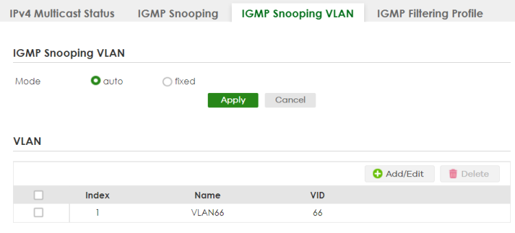
The following table describes the labels in this screen.
label | description |
|---|---|
IGMP Snooping VLAN | |
Mode | Select auto to have the Switch learn multicast group membership information of any VLANs automatically. Select fixed to have the Switch only learn multicast group membership information of the VLANs that you specify below. In either auto or fixed mode, the Switch can learn up to 16 VLANs (including up to five VLANs you configured in the MVR screen). For example, if you have configured one multicast VLAN in the SWITCHING > Multicast > MVR screen, you can only specify up to 15 VLANs in this screen. The Switch drops any IGMP control messages which do not belong to these 16 VLANs. You must also enable IGMP snooping in the SWITCHING > Multicast > IPv4 Multicast > IGMP Snooping screen first. |
Apply | Click Apply to save your changes to the Switch’s run-time memory. The Switch loses these changes if it is turned off or loses power, so use the Save link on the top navigation panel to save your changes to the non-volatile memory when you are done configuring. |
Cancel | Click Cancel to begin configuring this screen afresh. |
VLAN Use this section of the screen to add VLANs on which the Switch is to perform IGMP snooping. | |
Index | This is the index number of the IGMP snooping VLAN entry in the table. |
Name | This field displays the descriptive name for this VLAN group. |
VID | This field displays the ID number of the VLAN group. |
Select an entry’s checkbox to select a specific entry. Otherwise, select the checkbox in the table heading row to select all entries. | |
Add/Edit | Click Add/Edit to create a new entry or edit a selected one. |
Delete | Click Delete to remove the selected entries. |
Add/Edit IGMP Snooping VLANs
This screen allows you to add an IGMP snooping VLAN or edit an existing one.
To access this screen, click the Add/Edit button or select an entry from the list and click the Add/Edit button.
SWITCHING > Multicast > IPv4 Multicast > IGMP Snooping VLAN > Add/Edit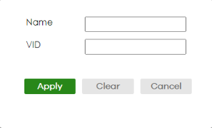
The following table describes the labels in this screen.
label | description |
|---|---|
Name | Enter the descriptive name of the VLAN for identification purposes. You can enter up to 32 printable ASCII characters except [ ? ], [ | ], [ ' ], [ " ] or [ , ]. |
VID | Enter the ID of a static VLAN; the valid range is between 1 and 4094. You cannot configure the same VLAN ID as in the SWITCHING > Multicast > MVR screen. |
Apply | Click Apply to save your changes to the Switch’s run-time memory. The Switch loses these changes if it is turned off or loses power, so use the Save link on the top navigation panel to save your changes to the non-volatile memory when you are done configuring. |
Clear | Click Clear to clear the fields to the factory defaults. |
Cancel | Click Cancel to not save the configuration you make and return to the last screen. |
IGMP Filtering Profile
An IGMP filtering profile specifies a range of multicast groups that clients connected to the Switch are able to join. A profile contains a range of multicast IP addresses which you want clients to be able to join. Profiles are assigned to ports (in the SWITCHING > Multicast > IPv4 Multicast > IGMP Snooping screen). Clients connected to those ports are then able to join the multicast groups specified in the profile. Each port can be assigned a single profile. A profile can be assigned to multiple ports.
Click SWITCHING > Multicast > IPv4 Multicast > IGMP Filtering Profile link to display the screen as shown.
SWITCHING > Multicast > IPv4 Multicast > IGMP Filtering Profile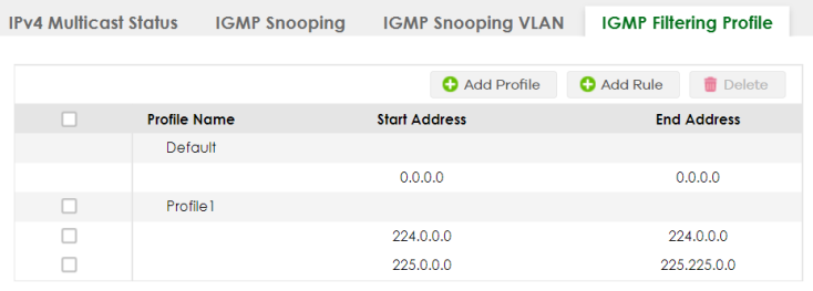
The following table describes the labels in this screen.
label | description |
|---|---|
Profile Name | This field displays the descriptive name of the profile. |
Start Address | This field displays the start of the multicast address range. |
End Address | This field displays the end of the multicast address range. |
Select an entry’s checkbox to select a specific entry. Otherwise, select the checkbox in the table heading row to select all entries. | |
Add Profile | Click this to add a new IGMP filtering profile. |
Add Rule | Click Add Rule to add a new rule and specify the profile it belongs to in the Add Rule screen. You can also select a profile entry and click Add Rule to add an additional rule for the selected profile. |
Delete | Select a profile and click Delete to remove the selected profile and the accompanying rules. Select a rule from a profile and click Delete to remove the selected rule. |
Add IGMP Filtering Profile
To access this screen, click the Add Profile button in the SWITCHING > Multicast > IPv4 Multicast > IGMP Filtering Profile screen.
SWITCHING > Multicast > IPv4 Multicast > IGMP Filtering Profile > Add Profile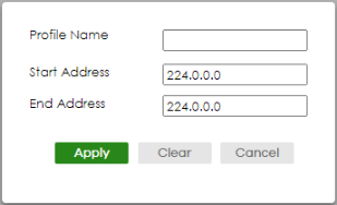
The following table describes the labels in this screen.
label | description |
|---|---|
Profile Name | Enter a descriptive name for the profile for identification purposes. You can enter up to 32 printable ASCII characters except [ ? ], [ | ], [ ' ], [ " ], or [ , ]. |
Start Address | Enter the starting multicast IP address for a range of multicast IP addresses that you want to belong to the IGMP filter profile. |
End Address | Enter the ending multicast IP address for a range of IP addresses that you want to belong to the IGMP filter profile. If you want to add a single multicast IP address, enter it in both the Start Address and End Address fields. |
Apply | Click Apply to save your changes to the Switch’s run-time memory. The Switch loses these changes if it is turned off or loses power, so use the Save link on the top navigation panel to save your changes to the non-volatile memory when you are done configuring. |
Clear | Click Clear to clear the fields to the factory defaults. |
Cancel | Click Cancel to not save the configuration you make and return to the last screen. |
Add IGMP Filtering Rule
Click Add Rule in the SWITCHING > Multicast > IPv4 Multicast > IGMP Filtering Profile screen to access this screen.
SWITCHING > Multicast > IPv4 Multicast > IGMP Filtering Profile > Add Rule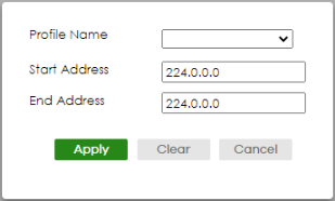
The following table describes the labels in this screen.
label | description |
|---|---|
Profile Name | Select a profile from the drop-down list to add a additional rule for the existing profile. |
Start Address | Enter the starting multicast IP address for a range of multicast IP addresses that you want to belong to the IGMP filter profile. |
End Address | Enter the ending multicast IP address for a range of IP addresses that you want to belong to the IGMP filter profile. If you want to add a single multicast IP address, enter it in both the Start Address and End Address fields. |
Apply | Click Apply to save your changes to the Switch’s run-time memory. The Switch loses these changes if it is turned off or loses power, so use the Save link on the top navigation panel to save your changes to the non-volatile memory when you are done configuring. |
Clear | Click Clear to clear the fields to the factory defaults. |
Cancel | Click Cancel to not save the configuration you make and return to the last screen. |
IPv6 Multicast Status
Click SWITCHING > Multicast > IPv6 Multicast > IPv6 Multicast Status to display the screen as shown. This screen shows the IPv6 multicast group information. See Multicast Overview for more information on multicasting.
SWITCHING > Multicast > IPv6 Multicast > IPv6 Multicast Status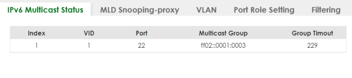
The following table describes the fields in the above screen.
label | description |
|---|---|
Index | This is the index number of the entry. |
VID | This field displays the multicast VLAN ID. |
Port | This field displays the port number that belongs to the multicast group. |
Multicast Group | This field displays IP multicast group addresses. |
Group Timeout | This field displays the time (in seconds) that elapses before the Switch removes a MLD group membership entry if it does not receive report messages from the port. |
MLD Snooping-proxy
Click SWITCHING > Multicast > IPv6 Multicast > MLD Snooping-proxy to display the screen as shown. See Multicast Overview for more information on multicasting.
SWITCHING > Multicast > IPv6 Multicast > MLD Snooping-proxy
The following table describes the fields in the above screen.
label | description |
|---|---|
MLD Snooping-proxy Use these settings to configure MLD snooping-proxy. | |
Active | Enable the switch button to enable MLD snooping-proxy on the Switch to minimize MLD control messages and allow better network performance. |
802.1p Priority | Select a priority level (0 – 7) to which the Switch changes the priority in outgoing MLD messages. |
Apply | Click Apply to save your changes to the Switch’s run-time memory. The Switch loses these changes if it is turned off or loses power, so use the Save link on the top navigation panel to save your changes to the non-volatile memory when you are done configuring. |
Cancel | Click Cancel to begin configuring this screen afresh. |
MLD Snooping-proxy VLAN
Click SWITCHING > Multicast > IPv6 Multicast > VLAN screen to display the screen as shown. See Multicast Overview for more information on multicasting.
SWITCHING > Multicast > IPv6 Multicast > VLAN: MLD Snooping-proxy VLAN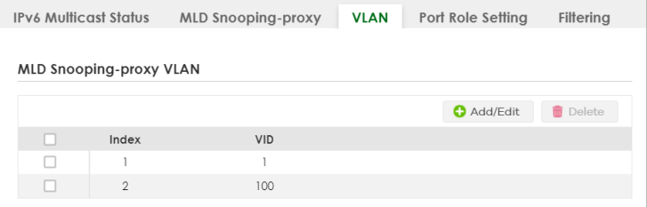
The following table describes the fields in the above screen.
label | description |
|---|---|
MLD Snooping-proxy VLAN | |
Index | This is the index number of the MLD snooping-proxy VLAN entry in the table. |
VID | This field displays the ID number of the VLAN group. |
Select an entry’s checkbox to select a specific entry. Otherwise, select the checkbox in the table heading row to select all entries. | |
Add/Edit | Click Add/Edit to add a new entry or edit a selected one. |
Delete | Click Delete to remove the selected entry. |
Add/Edit MLD Snooping-proxy VLAN
The screen allows you to enable and configure MLD Snooping-proxy settings on a VLAN you specified.
Click Add/Edit in the SWITCHING > Multicast > IPv6 Multicast > VLAN screen to display this screen.
SWITCHING > Multicast > IPv6 Multicast > VLAN > Add/Edit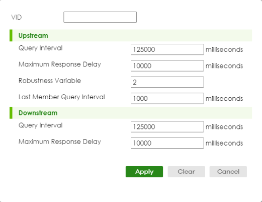
The following table describes the fields in the above screen.
label | description |
|---|---|
VID | Enter the ID number of the VLAN on which you want to enable MLD snooping-proxy and configure related settings. |
Upstream | |
Query Interval | Enter the amount of time (in miliseconds) between general query messages sent by the router connected to the upstream port. This value should be exactly the same as what is configured in the connected multicast router. This value is used to calculate the amount of time an MLD snooping membership entry (learned only on the upstream port) can remain in the forwarding table. When an MLD Report message is received, the Switch sets the timeout period of the entry to be T = (QI*RV) + MRD, where T = Timeout, QI = Query Interval, RV = Robustness Variable, and MRD = Maximum Response Delay. |
Maximum Response Delay | Enter the amount of time (in miliseconds) the router connected to the upstream port waits for a response to an MLD general query message. This value should be exactly the same as what is configured in the connected multicast router. This value is used to calculate the amount of time an MLD snooping membership entry (learned only on the upstream port) can remain in the forwarding table. When an MLD Report message is received, the Switch sets the timeout period of the entry to be T = (QI*RV) + MRD, where T = Timeout, QI = Query Interval, RV = Robustness Variable, and MRD = Maximum Response Delay. When an MLD Done message is received, the Switch sets the entry’s lifetime to be the product of Last Member Query Interval and Robustness Variable. |
Robustness Variable | Enter the number of queries. A multicast address entry (learned only on an upstream port by snooping) is removed from the forwarding table when there is no response to the configured number of queries sent by the router connected to the upstream port. This value should be exactly the same as what’s configured in the connected multicast router. This value is used to calculate the amount of time an MLD snooping membership entry (learned only on the upstream port) can remain in the forwarding table. |
Last Member Query Interval | Enter the amount of time (in miliseconds) between the MLD group-specific queries sent by an upstream port when an MLD Done message is received. This value should be exactly the same as what’s configured in the connected multicast router. This value is used to calculate the amount of time an MLD snooping membership entry (learned only on the upstream port) can remain in the forwarding table after a Done message is received. When an MLD Done message is received, the Switch sets the entry’s lifetime to be the product of Last Member Query Interval and Robustness Variable. |
Downstream | |
Query Interval | Enter the amount of time (in miliseconds) between general query messages sent by the downstream port. |
Maximum Response Delay | Enter the maximum time (in miliseconds) that the Switch waits for a response to a general query message sent by the downstream port. |
Apply | Click Apply to save your changes to the Switch’s run-time memory. The Switch loses these changes if it is turned off or loses power, so use the Save link on the top navigation panel to save your changes to the non-volatile memory when you are done configuring. |
Clear | Click Clear to clear the fields to the factory defaults. |
Cancel | Click Cancel to not save the configuration you make and return to the last screen. |
MLD Snooping-proxy Port Role Setting
Click SWITCHING > Multicast > IPv6 Multicast > Port Role Setting to display the screen as shown. See Multicast Overview for more information on multicasting.
SWITCHING > Multicast > IPv6 Multicast > Port Role Setting (Standalone Mode)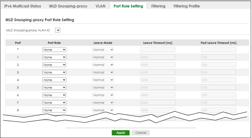
The following table describes the fields in the above screen.
label | description |
|---|---|
MLD Snooping-proxy Port Role Setting | |
MLD Snooping-proxy VLAN ID | Select the VLAN ID for which you want to configure a port’s MLD snooping-proxy settings. |
Port | This field displays the port number. |
* | Settings in this row apply to all ports. Use this row only if you want to make some settings the same for all ports. Use this row first to set the common settings and then make adjustments on a port-by-port basis. Changes in this row are copied to all the ports as soon as you make them. |
Port Role | A port on the Switch can be either a Downstream port or Upstream port in MLD. A downstream port connects to MLD hosts and acts as a multicast router to send MLD queries and listen to the MLD host’s Report and Done messages. An upstream port connects to a multicast router and works as a host to send Report or Done messages when receiving queries from a multicast router. Otherwise, select None if the port is not joining a multicast group or does not belong to this VLAN. |
Leave Mode | This is configurable only when you select Downstream in the previous Port Role field. Select the leave mode for the specified downstream ports in this VLAN. This specifies whether the Switch removes an MLD snooping membership entry (learned on a downstream port) immediately (Immediate) or wait for an MLD report before the leave timeout (Normal) or fast leave timeout (Fast) when an MLD leave message is received on this port from a host. |
Leave Timeout (ms) | Enter the MLD snooping normal leave timeout (in milliseconds) the Switch uses to update the forwarding table for the specified downstream ports. This defines how many seconds the Switch waits for an MLD report before removing an MLD snooping membership entry (learned on a downstream port) when an MLD Done message is received on this port from a host. |
Fast Leave Timeout (ms) | Enter the fast leave timeout (in milliseconds) for the specified downstream ports. This defines how many seconds the Switch waits for an MLD report before removing an MLD snooping membership entry (learned on a downstream port) when an MLD Done message is received on this port from a host. |
Apply | Click Apply to save your changes to the Switch’s run-time memory. The Switch loses these changes if it is turned off or loses power, so use the Save link on the top navigation panel to save your changes to the non-volatile memory when you are done configuring. |
Cancel | Click Cancel to reset the fields to your previous configuration. |
MLD Snooping-proxy Filtering
Use this screen to configure the Switch’s MLD filtering settings. Click the SWITCHING > Multicast > IPv6 Multicast > Filtering screen to display the screen as shown.
SWITCHING > Multicast > IPv6 Multicast > Filtering (Standalone Mode)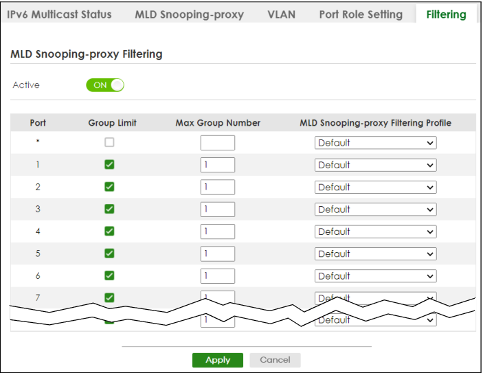
The following table describes the fields in the above screen.
label | description |
|---|---|
MLD Snooping-proxy Filtering | |
Active | Enable the switch button to enable MLD filtering on the Switch. |
Port | This field displays the port number. |
* | Settings in this row apply to all ports. Use this row only if you want to make some settings the same for all ports. Use this row first to set the common settings and then make adjustments on a port-by-port basis. Changes in this row are copied to all the ports as soon as you make them. |
Group Limit | Select this option to limit the number of multicast groups this port is allowed to join. |
Max Group Number | Enter the number of multicast groups this port is allowed to join. Once a port is registered in the specified number of multicast groups, any new MLD Report message is dropped on this port. |
MLD Snooping-proxy Filtering Profile | Select the name of the MLD filtering profile to use for this port. Otherwise, select Default to prohibit the port from joining any multicast group. You can create MLD filtering profiles in the SWITCHING > Multicast > IPv6 Multicast > Filtering Profile screen. |
Apply | Click Apply to save your changes to the Switch’s run-time memory. The Switch loses these changes if it is turned off or loses power, so use the Save link on the top navigation panel to save your changes to the non-volatile memory when you are done configuring. |
Cancel | Click Cancel to reset the fields to your previous configuration. |
MLD Snooping-proxy Filtering Profile
Use this screen to view and create MLD filtering profiles.
Click SWITCHING > Multicast > IPv6 Multicast > Filtering Profile to display the screen as shown.
SWITCHING > Multicast > IPv6 Multicast > Filtering Profile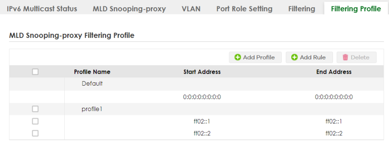
The following table describes the fields in the above screen.
Label | description |
|---|---|
MLD Snooping-proxy Filtering Profile | |
Profile Name | This field displays the descriptive name of the profile. |
Start Address | This field displays the start of the multicast IPv6 address range. |
End Address | This field displays the end of the multicast IPv6 address range. |
Select an entry’s checkbox to select a specific entry. Otherwise, select the checkbox in the table heading row to select all entries. | |
Add Profile | Click this to add a new MLD Snooping-proxy filtering profile. |
Add Rule | Click Add Rule to add a new rule and specify the profile it belongs to in the Add Rule screen. You can also select a profile entry and click Add Rule to add an additional rule for the selected profile. |
Delete | Select a profile and click Delete to remove the selected profile and the accompanying rules. Select a rule from a profile and click Delete to remove the selected rule. |
Add MLD Snooping-proxy Filtering Profile
Use this screen to create an MLD filtering profile and set the range of the multicast addresses.
Click Add Profile in the SWITCHING > Multicast > IPv6 Multicast > Filtering Profile to display the screen as shown.
SWITCHING > Multicast > IPv6 Multicast > Filtering Profile > Add Profile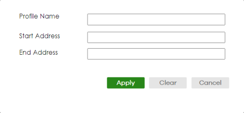
The following table describes the fields in the above screen.
Label | description |
|---|---|
Profile Name | Enter a descriptive name (up to 32 printable ASCII characters except [?], [|], [‘], [“], or [,]) for the profile for identification purposes. To configure additional rules for a profile that you have already added, enter the profile name and specify a different IP multicast address range. |
Start Address | Enter the starting multicast IPv6 address for a range of multicast IPv6 addresses that you want to belong to the MLD filtering profile. |
End Address | Enter the ending multicast IPv6 address for a range of IPv6 addresses that you want to belong to the MLD filtering profile. If you want to add a single multicast IPv6 address, enter it in both the Start Address and End Address fields. |
Apply | Click Apply to save your changes to the Switch’s run-time memory. The Switch loses these changes if it is turned off or loses power, so use the Save link on the top navigation panel to save your changes to the non-volatile memory when you are done configuring. |
Clear | Click Clear to clear the fields to the factory defaults. |
Cancel | Click Cancel to not save the configuration you make and return to the last screen. |
Add MLD Snooping-proxy Filtering Rule
Use this screen to create a multicast addresses range rule of the MLD filtering profile.
Click Add Rule in the SWITCHING > Multicast > IPv6 Multicast > Filtering Profile to display this screen.
SWITCHING > Multicast > IPv6 Multicast > Filtering Profile > Add Rule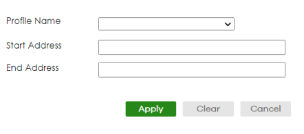
The following table describes the fields in the above screen.
Label | description |
|---|---|
Profile Name | Select a profile from the drop-down list to add a additional rule for the existing profile. |
Start Address | Enter the starting multicast IPv6 address for a range of multicast IPv6 addresses that you want to belong to the MLD filtering profile. |
End Address | Enter the ending multicast IPv6 address for a range of IPv6 addresses that you want to belong to the MLD filtering profile. If you want to add a single multicast IPv6 address, enter it in both the Start Address and End Address fields. |
Apply | Click Apply to save your changes to the Switch’s run-time memory. The Switch loses these changes if it is turned off or loses power, so use the Save link on the top navigation panel to save your changes to the non-volatile memory when you are done configuring. |
Clear | Click Clear to clear the fields to the factory defaults. |
Cancel | Click Cancel to not save the configuration you make and return to the last screen. |
MVR Configuration
Use this screen to view and create multicast VLANs.
Click SWITCHING > Multicast > MVR > MVR to display the screen as shown next.
You can create up to five multicast VLANs and up to 256 multicast rules on the Switch.Your Switch automatically creates a static VLAN (with the same VID) when you create a multicast VLAN in this screen.SWITCHING > Multicast > MVR > MVR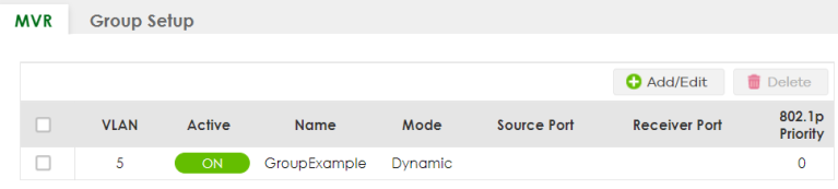
The following table describes the related labels in this screen.
label | description |
|---|---|
VLAN | This field displays the multicast VLAN ID. |
Active | This field displays whether the multicast group is enabled or not. |
Name | This field displays the descriptive name for this setting. |
Mode | This field displays the MVR mode. |
Source Port | This field displays the source port numbers. |
Receiver Port | This field displays the receiver port numbers. |
802.1p Priority | This field displays the priority level. |
Select an entry’s checkbox to select a specific entry. Otherwise, select the checkbox in the table heading row to select all entries. | |
Add/Edit | Click Add/Edit to add a new multicast VLAN or edit a selected one. |
Delete | Select the entries that you want to remove, then click Delete to delete multicast VLANs. |
Add/Edit MVR
Use this screen to create or edit multicast VLANs and select the receiver ports and a source port for each multicast VLAN.
To access this screen, click Add/Edit or select an existing entry and click Add/Edit in the SWITCHING > Multicast > MVR > MVR screen.
SWITCHING > Multicast > MVR > MVR > Add/Edit (Standalone Mode)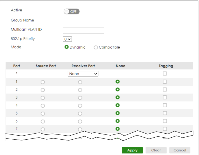
The following table describes the related labels in this screen.
label | description |
|---|---|
Active | Enable the switch button to enable MVR to allow one single multicast VLAN to be shared among different subscriber VLANs on the network. |
Group Name | Enter a descriptive name (up to 32 printable ASCII characters except [ ? ], [ | ], [ ' ], [ " ], or [ , ]) for identification purposes. |
Multicast VLAN ID | Enter the VLAN ID (1 to 4094) of the multicast VLAN. |
802.1p Priority | Select a priority level (0 – 7) with which the Switch replaces the priority in outgoing IGMP or MLD control packets (belonging to this multicast VLAN). |
Mode | Specify the MVR mode on the Switch. Choices are Dynamic and Compatible. Select Dynamic to send IGMP reports or MLD messages to all MVR source ports in the multicast VLAN. Select Compatible to set the Switch not to send IGMP reports or MLD messages. |
Use this section to configure MVR settings on each port. | |
Port | This field displays the port number on the Switch. |
* | Settings in this row apply to all ports. Use this row only if you want to make some settings the same for all ports. Use this row first to set the common settings and then make adjustments on a port-by-port basis. Changes in this row are copied to all the ports as soon as you make them. |
Source Port | Select this option to set this port as the MVR source port that sends and receives multicast traffic. All source ports must belong to a single multicast VLAN. |
Receiver Port | Select this option to set this port as a receiver port that only receives multicast traffic. |
None | Select this option to set the port not to participate in MVR. No MVR multicast traffic is sent or received on this port. |
Tagging | Select this checkbox if you want the port to tag the VLAN ID in all outgoing frames transmitted. |
Apply | Click Apply to save your changes to the Switch’s run-time memory. The Switch loses these changes if it is turned off or loses power, so use the Save link on the top navigation panel to save your changes to the non-volatile memory when you are done configuring. |
Clear | Click Clear to clear the fields to the factory defaults. |
Cancel | Click Cancel to not save the configuration you make and return to the last screen. |
MVR Group Setup
All source ports and receiver ports belonging to a multicast group can receive multicast data sent to this multicast group.
Use this screen to view and configure MVR IP multicast group settings. Click SWITCHING > Multicast > MVR > Group Setup to access this screen.
A port can belong to more than one multicast VLAN. However, IP multicast group addresses in different multicast VLANs cannot overlap.SWITCHING > Multicast > MVR > Group Setup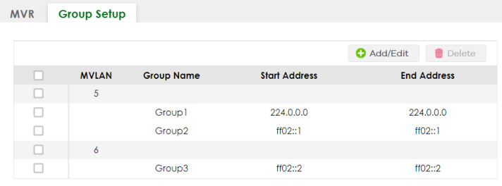
The following table describes the labels in this screen.
label | description |
|---|---|
MVLAN | This field displays the multicast VLAN ID. |
Group Name | This field displays the descriptive name for this setting. |
Start Address | This field displays the starting IP address of the multicast group. |
End Address | This field displays the ending IP address of the multicast group. |
Select an entry’s checkbox to select a specific entry. Otherwise, select the checkbox in the table heading row to select all entries. | |
Add/Edit | Click Add/Edit to add a new multicast group or edit a selected one. |
Delete | Select the group entries that you want to remove, then click Delete to delete the selected multicast groups. If you delete a multicast VLAN, all multicast groups in this VLAN will also be removed. |
Add/Edit MVR Group
Use this screen to configure MVR IP multicast group addresses. To access this screen, click the Add/Edit button or select an entry from the list and click the Add/Edit button.
SWITCHING > Multicast > MVR > Group Setup > Add/Edit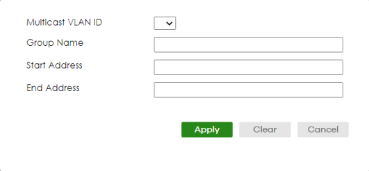
The following table describes the labels in this screen.
label | description |
|---|---|
Multicast VLAN ID | Select a multicast VLAN ID (that you configured in the MVR screen) from the drop-down list box. |
Group Name | Enter a descriptive name for identification purposes. You can enter up to 32 printable ASCII characters except [ ? ], [ | ], [ ' ], [ " ], or [ , ]. |
Start Address | Enter the starting IP multicast address of the multicast group in dotted decimal notation. |
End Address | Enter the ending IP multicast address of the multicast group in dotted decimal notation. Enter the same IP address as the Start Address field if you want to configure only one IP address for a multicast group. |
Apply | Click Apply to save your changes to the Switch’s run-time memory. The Switch loses these changes if it is turned off or loses power, so use the Save link on the top navigation panel to save your changes to the non-volatile memory when you are done configuring. |
Clear | Click Clear to clear the fields to the factory defaults. |
Cancel | Click Cancel to not save the configuration you make and return to the last screen. |
MVR Configuration Example
The following figure shows a network example where ports 1, 2 and 3 on the Switch belong to VLAN 1. In addition, port 23 belongs to the multicast group with VID 200 (MVID 200) to receive multicast traffic (the News (N) and Movie (M) channels) from the remote streaming media server (S). Computers A, B and C in VLAN 1 are able to receive the traffic.
MVR Configuration Example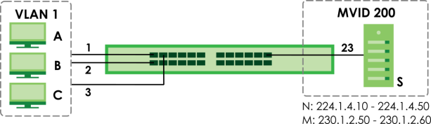
To configure the MVR settings on the Switch, click the Add/Edit button in the SWITCHING > Multicast > MVR > MVR screen. Create a multicast VLAN and set the receiver and source ports.
MVR Configuration Example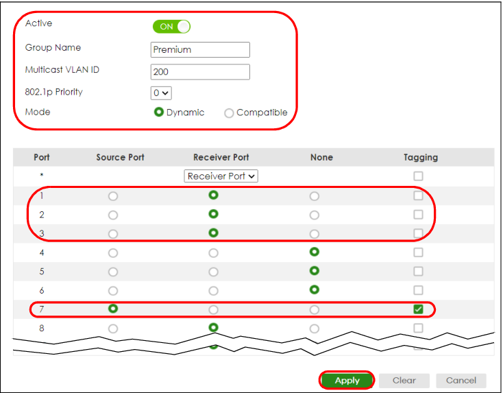
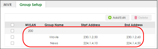
To set the Switch to forward the multicast group traffic to the subscribers, click Add/Edit in the SWITCHING > Multicast > MVR > Group Setup screen and configure multicast group settings. The following figure shows an example where two IPv4 multicast groups (News and Movie) are configured for the multicast VLAN 200.
MVR Group Configuration Example – Add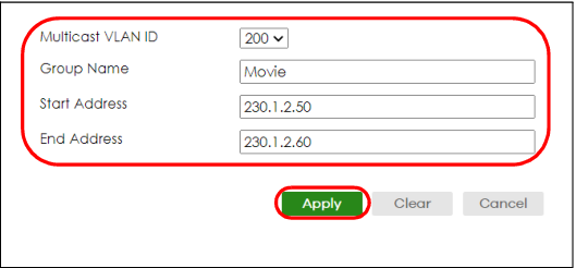
MVR Group Configuration Example – View