VLAN Mapping
This chapter shows you how to configure VLAN mapping on the Switch.
VLAN Mapping Overview
With VLAN mapping enabled, the Switch can map the VLAN ID and priority level of packets received from a private network to those used in the service provider’s network.
The Switch checks incoming traffic from the switch ports (non-management ports) against the VLAN mapping table first, the MAC learning table and then the VLAN table before forwarding them through the Gigabit uplink port. When VLAN mapping is enabled, the Switch discards the tagged packets that do not match an entry in the VLAN mapping table. If the incoming packets are untagged, the Switch adds a PVID based on the VLAN setting.
 You cannot enable VLAN mapping and VLAN stacking at the same time.
VLAN Mapping Example
In the following example figure, packets that carry VLAN ID 12 and are received on port 3 (P3) match a pre-configured VLAN mapping rule. The Switch translates the VLAN ID from 12 into 123 before forwarding the packets. Any packets carrying a VLAN tag other than 12 (such as 10) and received on port 3 (P3) will be dropped.
VLAN Mapping Example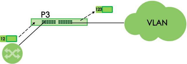
What You Can Do
Enable VLAN Mapping
Click SWITCHING > VLAN Mapping > VLAN Mapping in the navigation panel to display the screen as shown.
SWITCHING > VLAN Mapping > VLAN Mapping (Standalone Mode)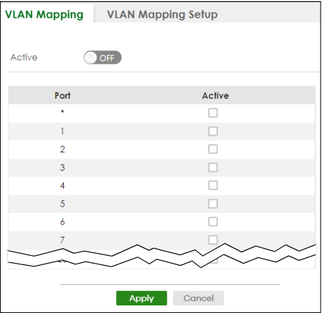
The following table describes the labels in this screen.
Label | Description |
|---|---|
Active | Enable the switch button to enable VLAN mapping on the Switch. |
Port | This field displays the port number. |
* | Settings in this row apply to all ports. Use this row only if you want to make some settings the same for all ports. Use this row first to set the common settings and then make adjustments on a port-by-port basis. Changes in this row are copied to all the ports as soon as you make them. |
Active | Select this checkbox to enable the VLAN mapping feature on this port. Clear this checkbox to disable the VLAN mapping feature. |
Apply | Click Apply to save your changes to the Switch’s run-time memory. The Switch loses these changes if it is turned off or loses power, so use the Save link on the top navigation panel to save your changes to the non-volatile memory when you are done configuring. |
Cancel | Click Cancel to begin configuring this screen afresh. |
VLAN Mapping Setup
Click the SWITCHING > VLAN Mapping > VLAN Mapping Setup to display the screen as shown. Use this screen to view and configure the VLAN mapping rules.
SWITCHING > VLAN Mapping > VLAN Mapping Setup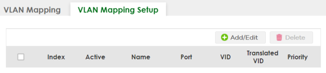
The following table describes the labels in this screen.
LABEL | DESCRIPTION |
|---|---|
Index | This is the number of the VLAN mapping entry in the table. |
Active | This shows whether this entry is activated or not. |
Name | This is the descriptive name for this rule. |
Port | This is the port number to which this rule is applied. |
VID | This is the customer VLAN ID in the incoming packets. |
Translated VID | This is the VLAN ID that replaces the customer VLAN ID in the tagged packets. |
Priority | This is the priority level that replaces the customer priority level in the tagged packets. |
Select an entry’s checkbox to select a specific entry. Otherwise, select the checkbox in the table heading row to select all entries. | |
Add/Edit | Click Add/Edit to add a new entry or edit a selected one. |
Delete | Click Delete to remove the selected entries. |
Add/Edit VLAN Mapping
Click Add/Edit, or select an entry and click Add/Edit in the SWITCHING > VLAN Mapping > VLAN Mapping Setup to display this screen. Use this screen to enable and edit the VLAN mapping rules.
SWITCHING > VLAN Mapping > VLAN Mapping Setup > Add/Edit (Standalone Mode)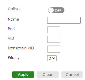
The following table describes the labels in this screen.
LABEL | DESCRIPTION |
|---|---|
Active | Enable the switch button to activate this rule. |
Name | Enter a descriptive name (up to 32 printable ASCII characters except [ ? ], [ | ], [ ' ], [ " ], or [ , ]) for identification purposes. |
Port | Type a port to be included in this rule. |
VID | Enter a VLAN ID from 1 to 4094. This is the VLAN tag carried in the packets and will be translated into the VID you specified in the Translated VID field. |
Translated VID | Enter a VLAN ID (from 1 to 4094) into which the customer VID carried in the packets will be translated. |
Priority | Select a priority level (from 0 to 7). This is the priority level that replaces the customer priority level in the tagged packets or adds to the untagged packets. |
Apply | Click Apply to save your changes to the Switch’s run-time memory. The Switch loses these changes if it is turned off or loses power, so use the Save link on the top navigation panel to save your changes to the non-volatile memory when you are done configuring. |
Clear | Click Clear to clear the fields to the factory defaults. |
Cancel | Click Cancel to not save the configuration you make and return to the last screen. |