IP Setup
IP Setup Overview
This chapter shows you how to configure IP settings and set up IP interfaces on the Switch using the IP Setup screens.
What You Can Do
• Use the IP Status screen (IP Status) to view the current IP interfaces and DNS server settings on the Switch.
• Use the IP Setup screen (IP Setup) to configure the default gateway device, the default domain name server and add IP domains.
• Use the Network Proxy Configuration screen (Network Proxy Configuration) to configure network proxy configurations.
IP Interfaces
The Switch needs an IP address for it to be managed over the network. When the Switch (in Standalone mode) fails to obtain an IP address from a DHCP server, the default static IP address 192.168.1.1 will be automatically added and used as the Switch’s management IP address. The subnet mask specifies the network number portion of an IP address. The factory default subnet mask is 255.255.255.0.
On the Switch, an IP address is not bound to any physical ports. Since each IP address on the Switch must be in a separate subnet, the configured IP address is also known as IP interface (or routing domain). In addition, this allows routing between subnets based on the IP address without additional routers.
You can configure multiple routing domains on the same VLAN as long as the IP address ranges for the domains do not overlap. To change the IP address of the Switch in a routing domain, simply add a new routing domain entry with a different IP address in the same subnet.
You can configure up to 128 IP domains which are used to access and manage the Switch from the ports belonging to the pre-defined VLANs.
 You must configure a VLAN first before adding a management IP address. Each VLAN can only have one management IP address. Each VLAN can have multiple management IP addresses, and you can log into the Switch through different management IP addresses simultaneously.
IP Status
Click SYSTEM > IP Setup > IP Status to display the screen as shown.
SYSTEM > IP Setup > IP Status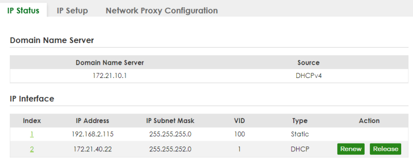
The following table describes the labels in this screen.
label | description |
|---|---|
Domain Name Server | |
Domain Name Server | This field displays the IP address of the DNS server. |
Source | This field displays whether the DNS server address is configured manually (Static) or obtained automatically using DHCPv4. |
IP Interface | |
Index | This field displays the index number of an entry. |
IP Address | This field displays the IP address of the Switch in the IP domain. |
IP Subnet Mask | This field displays the subnet mask of the Switch in the IP domain. |
VID | This field displays the VLAN identification number of the IP domain on the Switch. |
Type | This shows whether this IP address is dynamically assigned from a DHCP server (DHCP) or manually assigned (Static). |
Renew | Click this to renew the dynamic IP address. |
Release | Click this to release the dynamic IP address. |
IP Status Details
Use this screen to view IP status details. Click a number in the Index column in the SYSTEM > IP Setup > IP Status screen to display the screen as shown next.
SYSTEM > IP Setup > IP Status > IP Status Details: Static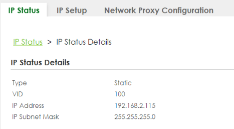
The following table describes the labels in this screen.
label | description |
|---|---|
Type | This shows the IP address is manually assigned (Static). |
VID | This is the VLAN identification number to which an IP routing domain belongs. |
IP Address | This is the IP address of your Switch in dotted decimal notation for example 192.168.1.1. |
IP Subnet Mask | This is the IP subnet mask of your Switch in dotted decimal notation for example 255.255.255.0. |
SYSTEM > IP Setup > IP Status > IP Status Details: DHCP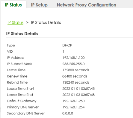
The following table describes the labels in this screen.
label | description |
|---|---|
Type | This shows the IP address is dynamically assigned from a DHCP server (DHCP). |
VID | This is the VLAN identification number to which an IP routing domain belongs. |
IP Address | This is the IP address of your Switch in dotted decimal notation for example 192.168.1.1. |
IP Subnet Mask | This is the IP subnet mask of your Switch in dotted decimal notation for example 255.255.255.0. |
Lease Time | This displays the length of time in seconds that this interface can use the current dynamic IP address from the DHCP server. |
Renew Time | This displays the length of time from the lease start that the Switch will request to renew its current dynamic IP address from the DHCP server. |
Rebind Time | This displays the length of time from the lease start that the Switch will request to get any dynamic IP address from the DHCP server. |
Lease Time Start | This displays the date and time that the current dynamic IP address assignment from the DHCP server began. You should configure date and time in SYSTEM > General Setup > General Setup. |
Lease Time End | This displays the date and time that the current dynamic IP address assignment from the DHCP server will end. You should configure date and time in SYSTEM > General Setup > General Setup. |
Default Gateway | This displays the IP address of the default gateway assigned by the DHCP server. 0.0.0.0 means no gateway is assigned. |
Primary / Secondary DNS Server | This displays the IP address of the primary and secondary DNS servers assigned by the DHCP server. 0.0.0.0 means no DNS server is assigned. |
IP Setup
Use this screen to configure the default gateway device, the default domain name server and add IP domains. Click SYSTEM > IP Setup > IP Setup in the navigation panel to display the screen as shown.
The Switch allows you to set a static IP interface in the same subnet that already has a DHCP-assigned IP interface on the Switch. The Switch will use the static IP you set and the DHCP-assigned IP will be set to 0.0.0.0.SYSTEM > IP Setup > IP Setup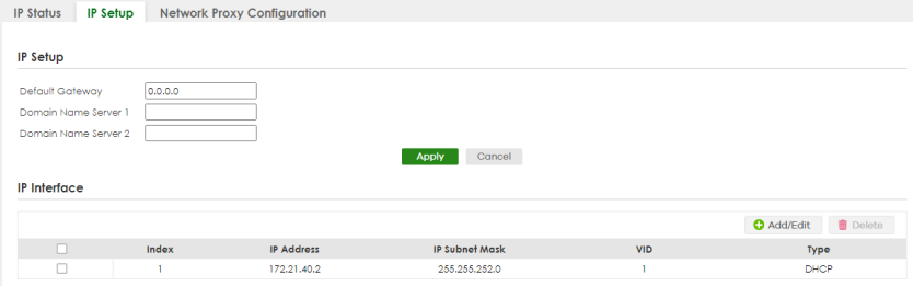
The following table describes the labels in this screen.
label | description |
|---|---|
IP Setup | |
Default Gateway | Type the IP address of the default outgoing gateway in dotted decimal notation, for example 192.168.1.254. |
Domain Name Server 1/2 | Enter a domain name server IPv4 address in order to be able to use a domain name instead of an IP address. |
Apply | Click Apply to save your changes to the Switch’s run-time memory. The Switch loses these changes if it is turned off or loses power, so use the Save link on the top navigation panel to save your changes to the non-volatile memory when you are done configuring. |
Cancel | Click Cancel to reset the fields to your previous configuration. |
IP Interface Use this section to view and configure IP routing domains on the Switch. | |
Index | This field displays the index number of an entry. |
IP Address | This field displays the IP address of the Switch in the IP domain. |
IP Subnet Mask | This field displays the subnet mask of the Switch in the IP domain. |
VID | This field displays the VLAN identification number of the IP domain on the Switch. |
Type | This field displays the type of IP address status. Static or DHCP. |
Select an entry’s checkbox to select a specific entry. Otherwise, select the checkbox in the table heading row to select all entries. | |
Add/Edit | Click Add/Edit to add a new IP interface or edit a selected one. |
Delete | Click Delete to remove the selected IP interfaces. |
Add/Edit IP Interfaces
Use this screen to add or edit IP interfaces. Click Add/Edit, or select an entry and click Add/Edit in the SYSTEM > IP Setup > IP Setup screen to display this screen.
SYSTEM > IP Setup > IP Setup > Add/Edit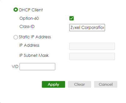
The following table describes the labels in this screen.
label | description |
|---|---|
DHCP Client | Select this option if you have a DHCP server that can assign the Switch an IP address, subnet mask, a default gateway IP address and a domain name server IP address automatically. |
Option-60 | DHCP Option 60 is used by the Switch for identification to the DHCP server using the VCI (Vendor Class Identifier) on the DHCP server. The Switch adds it in the initial DHCP discovery message that a DHCP client broadcasts in search of an IP address. The DHCP server can assign different IP addresses or options to clients with the specific VCI or reject the request from clients without the specific VCI. Select this and enter the device identity you want the Switch to add in the DHCP discovery frames that go to the DHCP server. This allows the Switch to identify itself to the DHCP server. |
Class-ID | Enter a string of up to 32 printable ASCII characters to identify this Switch to the DHCP server. For example, Zyxel-TW. The string should not contain [ ? ], [ | ], [ ' ], [ " ], or [ , ]. |
Static IP Address | Select this option if you do not have a DHCP server or if you wish to assign static IP address information to the Switch. You need to fill in the following fields when you select this option. |
IP Address | Enter the IP address of your Switch in dotted decimal notation, for example, 192.168.1.1. This is the IP address of the Switch in an IP routing domain. |
IP Subnet Mask | Enter the IP subnet mask of an IP routing domain in dotted decimal notation, for example, 255.255.255.0. |
VID | Enter the VLAN identification number to which an IP routing domain belongs. |
Apply | Click Apply to save your changes to the Switch’s run-time memory. The Switch loses these changes if it is turned off or loses power, so use the Save link on the top navigation panel to save your changes to the non-volatile memory when you are done configuring. |
Clear | Click Clear to clear the fields to the factory defaults. |
Cancel | Click Cancel to not save the configuration you make and return to the last screen. |
Network Proxy Configuration
The proxy server of an organization may prohibit communication between the Switch and NCC (Nebula Control Center). Use this screen to enable communication between the Switch and NCC through the proxy server (P).
Network Proxy Configuration Application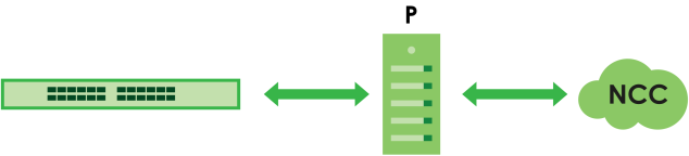
As of this writing, this setting only allows communication between the Switch and the NCC.
SYSTEM > IP Setup > Network Proxy Configuration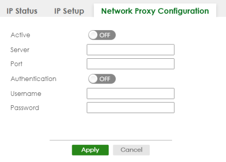
The following table describes the labels in this screen.
label | description |
|---|---|
Active | Enable the switch button to enable communication between the Switch and NCC through a proxy server. |
Server | Enter the IP address (dotted decimal notation) or host name of the proxy server. When entering the host name, up to 128 alphanumeric characters are allowed for the Server except [ ? ], [ | ], [ ' ], or [ " ]. |
Port | Enter the port number of the proxy server (1 – 65535). |
Authentication | Enable the switch button to enable proxy server authentication using a Username and Password. |
Username | Enter a login user name from the proxy server administrator. Up to 32 alphanumeric characters are allowed for the Username. The string should not contain [ ? ], [ | ], [ ' ], [ " ], [ , ], [ : ], or space. |
Password | Enter a login password from the proxy server administrator. Up to 32 alphanumeric characters are allowed for the Password except [ ? ], [ | ], [ ' ], and [ " ]. |
Apply | Click Apply to save your changes to the Switch’s run-time memory. The Switch loses these changes if it is turned off or loses power, so use the Save link on the top navigation panel to save your changes to the non-volatile memory when you are done configuring. |
Cancel | Click Cancel to reset the fields to your previous configuration. |