Getting to Know Your Switch
Introduction
This User Guide is for the platform version listed on the cover. This chapter introduces the main features and applications of the Switch.
The XMG2230 Series consists of the following models:
• XMG2230-28HP
• XMG2230-52HP
All models are referred to as the “Switch” in this guide.
The Switch supports NebulaFlex for hybrid mode which can set the Switch to operate in either standalone or Nebula cloud management mode. When the Switch is in standalone mode, it can be configured and managed by the Web Configurator. When the Switch is in Nebula cloud management mode, it can be managed and provisioned by the Zyxel Nebula Control Center (NCC).
The last four 10G ports can also be used for stacking. Use the four 10G fiber ports. When working in stacking mode, the Switch can operate together with other Switches of the same model and firmware version and allows you to remotely manage them from one switch using one single IP address.
The Switch uses redundant power supplies, AC power and DC power, to ensure no Switch downtimes in case of a power supply outage.
Multi-Gigabit
A 2.5 Gigabit port supports speeds of 2.5G if the connected device supports 2.5G and a Cat 5e (up to 100 m) is used. The speed drops to 1G if these criteria are not met.
If a network device such as a 5G network card, gaming computer, server, Network Attached Storage (NAS) or Access Point (AP) only supports 1 Gigabit connectivity, then the maximum speed potential of these devices is never reached.
Multi-Gigabit (IEEE 802.3bz) solves these problems by additionally supporting 1 Gigabit and 2.5 Gigabit Ethernet connections over Cat 5e and higher Ethernet cables.
Multi-Gigabit Application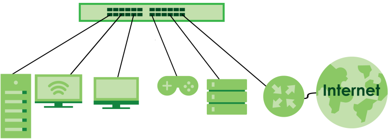
See the following table for the cables required and distance limitation to attain the corresponding speed.
Cable | transmission speed | maximum Distance | BANDWIDTH CAPACITY |
|---|---|---|---|
Category 5 | 100M | 100 m | 100 MHz |
Category 5e or better | 1G / 2.5G | 100 m | 100 MHz |
Example Applications
This section shows a few examples of using the Switch in various network environments. Note that the Switch in the figure is just an example Switch and not your actual Switch.
PoE Example Application
The following example figure shows a Switch supplying PoE (Power over Ethernet) to Powered Devices (PDs) such as an IP camera, a wireless router, an IP telephone and a general outdoor router that are not within reach of a power outlet.
PoE Example Application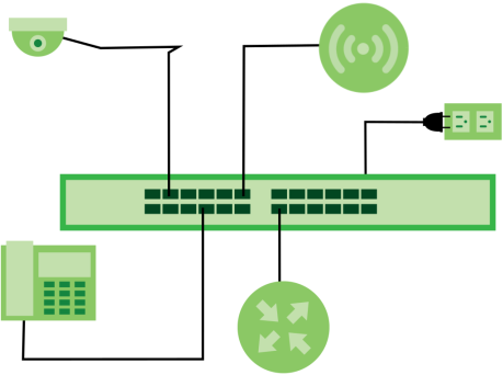
Backbone Example Application
The Switch is an ideal solution for small networks where rapid growth can be expected in the near future. The Switch can be used standalone for a group of heavy traffic users. You can connect computers and servers directly to the Switch’s port or connect other switches to the Switch.
In this example, all computers can share high-speed applications on the server. To expand the network, simply add more networking devices such as switches, routers, computers, print servers, and so on.
Backbone Application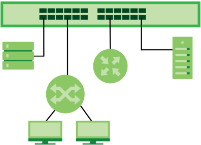
Bridging with Fiber Optic Uplink Example Application
In this example, the Switch connects different company departments (RD and Sales (S)) to the corporate backbone. It can alleviate bandwidth contention and eliminate server and network bottlenecks. All users that need high bandwidth can connect to high-speed department servers through the Switch.
Moreover, the Switch eases supervision and maintenance by allowing network managers to centralize multiple servers at a single location.
Bridging with Fiber Optic Uplink Example Application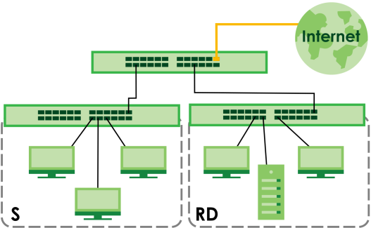
High Performance Switching Example
The Switch is ideal for connecting two geographically dispersed networks that need high bandwidth. In the following example, a company uses the 10 Gigabit uplink ports to connect the headquarters to a branch office network. Within the headquarters network, a company can use trunking to group several physical ports into one logical higher-capacity link. Trunking can be used if for example, it is cheaper to use multiple lower-speed links than to under-utilize a high-speed, but more costly, single-port link.
High Performance Switching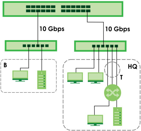
IEEE 802.1Q VLAN Application Examples
A VLAN (Virtual Local Area Network) allows a physical network to be partitioned into multiple logical networks. Stations on a logical network belong to one or more groups. With VLAN, a station cannot directly talk to or hear from stations that are not in the same groups unless such traffic first goes through a router.
Tag-based VLAN Example
Ports in the same VLAN group share the same frame broadcast domain thereby increase network performance through reduced broadcast traffic. VLAN groups can be modified at any time by adding, moving or changing ports without any re-cabling.
Shared resources such as a server can be used by all ports in the same VLAN as the server. In the following figure only ports that need access to the server need to be part of VLAN 1. Ports can belong to other VLAN groups too.
Shared Server Using VLAN Example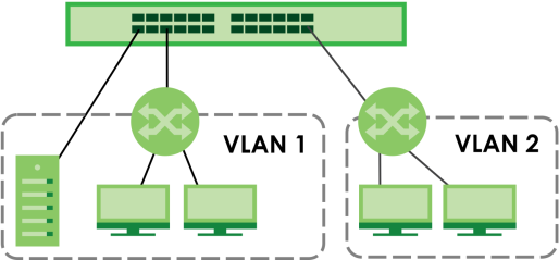
IPv6 Support
IPv6 (Internet Protocol version 6), is designed to enhance IP address size and features. The increase in IPv6 address size to 128 bits (from the 32-bit IPv4 address) allows up to 3.4 x 1038 IP addresses. At the time of writing, the Switch supports the following features.
• Static address assignment and stateless auto-configuration
• Neighbor Discovery Protocol (a protocol used to discover other IPv6 devices in a network)
• Remote Management using ping, SNMP, SSH, telnet, HTTP and FTP services
• ICMPv6 to report errors encountered in packet processing and perform diagnostic functions, such as "ping”
• IPv4/IPv6 dual stack; the Switch can run IPv4 and IPv6 at the same time
• DHCPv6 client and relay
• Multicast Listener Discovery (MLD) snooping and proxy
Ways to Manage the Switch
Use any of the following methods to manage the Switch.
• NCC (Zyxel Nebula Control Center). With the NCC, you can remotely manage and monitor the Switch through a cloud-based network management system. See the NCC User’s Guide for detailed information on how to access the NCC, manage your Switch through the NCC, and configure Nebula managed devices.
• Web Configurator. This is recommended for everyday management of the Switch using a (supported) web browser.
• Command Line Interface. Line commands offer an alternative to the Web Configurator and in some cases are necessary to configure advanced features. See the CLI Reference Guide.
• FTP. Use File Transfer Protocol for firmware upgrades and configuration backup or restore.
• SNMP. The Switch can be monitored and/or managed by an SNMP manager.
• Cluster Management. Cluster Management allows you to manage multiple switches through one switch, called the cluster manager.
• ZON Utility. ZON Utility is a program designed to help you deploy and perform initial setup on a network more efficiently.
Management Modes
The Switch can operate in either standalone or Nebula cloud management mode. When the Switch is in standalone mode, it can be configured and managed by the Web Configurator. When the Switch is in Nebula cloud management mode, it can be managed and provisioned by the Zyxel Nebula Control Center (NCC).
Use the DHCP-assigned IP address or 192.168.1.1 to access the Web Configurator. To know the IP address, use the NCC, the ZON utility, or the console port if available. You can also use the domain name “setup.zyxel” to access the Web Configurator when you are directly connected to the Switch.
Use the Web Configurator to configure and manage the Switch directly in standalone mode or use Nebula Control Center (NCC) to configure and manage the Switch in cloud mode. The Nebula Control Center (NCC) is an alternative cloud-based network management system that allows you to remotely manage and monitor the Zyxel Nebula Security Appliances (SA), Ethernet Switches (S1 and S2), and Access Points (AP). You may also access the Web Configurator in cloud mode.
NCC Example Network Topology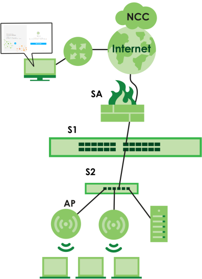
Nebula Cloud Management
To have Nebula manage the Switch, you must first register it at the Nebula web portal at https://nebula.zyxel.com, and ensure that Nebula Control Center (NCC) Discovery is enabled in SYSTEM > Cloud Management in the Switch Web Configurator.
See the NCC User’s Guide for how to configure the Switch using Nebula.
Mode Changing
This section describes how to change the Switch’s management mode. Refer to the Switch’s standalone mode User’s Guide for LED descriptions, including CLOUD LED behavior.
From Standalone to Nebula Cloud Management
To manage your Switch through Nebula, connect the Switch to the Internet, and register it to a site and organization at the Nebula web portal (https://nebula.zyxel.com).
See the following steps or the Switch Quick Start Guide for registering the Switch.
Go to the NCC to Register the Switch
1 Go to the Nebula web portal in one of three ways.
• Enter https://nebula.zyxel.com in a supported web browser. See the Nebula User’s Guide for more information about supported browsers.
• Click Visit Nebula in the Switch’s login page.
• Click the Nebula Control Center icon in the upper right of the Switch’s Web Configurator.
2 Click Get Started in the Nebula web portal. Enter your Zyxel Account information. You will be redirected to another screen where you can sign up for a Zyxel Account if you do not have one.
3 Create an organization and a site (using the Nebula setup wizard) or select an existing site.
4 Register the Switch by entering its Registration MAC address and serial number and assign it to the site. The serial number and Registration MAC address can be found in the DASHBOARD screen or the device back label on the Switch.
Use the Zyxel Nebula Mobile App to Register the Switch
1 Download and open the Zyxel Nebula Mobile app in your mobile device (see Section 19.2 on page 157 to download the app). Click Start on the first page. Click Create account to create a Zyxel Account or enter your existing account information to log in.
2 Create an organization and site, or select an existing site using the Zyxel Nebula Mobile app.
3 Select a site and scan the Switch's QR code or manually enter the information to add it to the site. You can find the QR code:
• On a label on the Switch or
• On its box or
• In the Web Configurator at SYSTEM > Cloud Management.
See Section 3.4 on page 56 for more information about the CLOUD LED or Section Table 31 on page 123 for more information about the Cloud Control Status field in the DASHBOARD screen to see if the Switch goes into Nebula cloud management mode successfully.
Local Credentials Password
The Switch goes into Cloud mode automatically after it can access the Nebula web portal and is successfully registered there. Its login password and settings are then overwritten with what you have configured in the Nebula web portal. To access the Web Configurator when the Switch is in Cloud mode, use the Local credentials password to login.
Site-wide > Configure > Site settings: Device configuration: Local credentials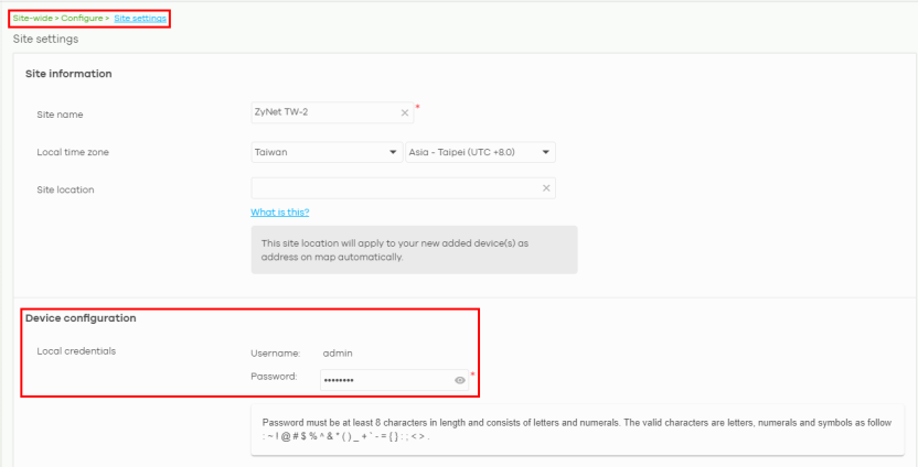
mode | access | login user name | login password | login ip address/URL/Domain name |
|---|---|---|---|---|
Cloud mode | NCC (Nebula Control Center) portal | Zyxel Account email | Zyxel Account password | https://nebula.zyxel.com |
Web Configurator (Local GUI) | admin | Local credentials password | https://setup.zyxel OR https://DHCP-assigned IP OR a configured static IP address | |
You can configure the Switch using both the NCC and the Web Configurator. • The settings you configure in the NCC will appear in the Web Configurator settings and will be applied to the Switch. • The settings you configure in the Web Configurator will not appear in the NCC settings, but will be applied to the Switch. To avoid inconsistency, we recommend you use NCC to configure the Switch. Only use the Web Configurator for advanced settings not available in the NCC or for troubleshooting if you cannot access the NCC. | ||||
Standalone mode | Web Configurator | admin | On the label on the back of the Switch | https://setup.zyxel OR https://DHCP-assigned IP OR https://192.168.1.1 |
From Nebula-managed to Standalone Mode
To return to direct management standalone mode, remove (unregister) the Switch from the inventory in the Nebula web portal.
To unregister the Switch:
1 Go to the Nebula Control Center (https://nebula.zyxel.com).
2 Go to the Organization-wide > License & inventory > Devices screen.
3 Select the Switch you want to remove (unregister) from the organization.
4 Click Actions, then click Remove from organization.
It will take a while for the Switch to reboot and reset to factory default.
Web Configurator Networked AV Mode
Aside from the Web Configurator in Standard mode, you can switch to Networked AV mode that is specifically designed to simplify configuration and management of the Switch for AVoIP (Audio-Video over Internet Protocol) application. In AV over IP, the AV transmitter is the transmitter, the AV receiver is the receiver, and the matrix switch is a standard IP Switch. See Section 4.4 on page 68 for details on using the Setup Wizard screen for configuring the Switch’s Networked AV mode’s basic and advanced settings.
Comparison Between Traditional AV and AVoIP Setups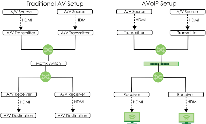
PoE
The Switch is a Power Sourcing Equipment (PSE) because it provides a source of power through its Ethernet ports. Each device that receives power through an Ethernet port is a Powered Device (PD).
The Switch can adjust the power supplied to each PD according to the PoE standard the PD supports. PoE standards are:
• IEEE 802.3af Power over Ethernet (PoE)
• IEEE 802.3at Power over Ethernet (PoE) +
• IEEE 802.3bt Power over Ethernet (PoE) ++
The following table describes the PoE features of the Switch by PoE standard.
pOe FEATURES | xMG2230-28HP | xMG2230-52HP |
|---|---|---|
IEEE 802.3at PoE+ | Ports 1 – 24 | Ports 1 – 48 |
IEEE 802.3bt PoE++ | Ports 1 – 24 | Ports 17 – 48 |
Power Management Mode | Consumption (default) Classification | Consumption (default) Classification |
PoE Power Budget | 700 W (Internal AC power) 1440 W (External DC power) | 960 W (Internal AC power) 2400 W (External DC power) |
Poe features | Poe | Poe+ | Poe++ |
|---|---|---|---|
IEEE Standard | IEEE 802.3af | IEEE 802.3at | IEEE 802.3bt |
PoE Type | Type 1 | Type 2 | Type 3 |
Switch Port Power | |||
IEEE Power Classification | Class 0, 1, 2, 3 | Class 4 | Class 5, 6 |
Maximum Power Per Port | 15.4 W | 30 W | 60 W |
Port Voltage Range | 44 – 57 V | 50 – 57 V | 50 – 57 V |
Cables | |||
Twisted Pairs Used | 2-pair | 2-pair | 4-pair |
Supported Cables | Cat3 or better | Cat5 or better | Cat5 or better |
•