PORT
The following sections introduce the PORT screens.
Link Aggregation
This section shows you how to logically aggregate physical links to form one logical, higher-bandwidth link.
Link aggregation (LA) (trunking) is the grouping of physical ports into one logical higher-capacity link (LL). You may want to trunk ports if for example, it is cheaper to use multiple lower-speed links than to under-utilize a high-speed, but more costly, single-port link. However, the more ports you aggregate then the fewer available ports you have. A trunk group is one logical link containing multiple ports.
The beginning port of each trunk group must be physically connected to form a trunk group.
Link Aggregation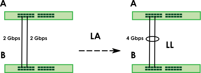
What You Can Do
• Use the Link Aggregation Status screen (Link Aggregation Status) to view ports you have configured to be in the trunk group, ports that are currently transmitting data as one logical link in the trunk group and so on.
• Use the Link Aggregation Setting screen (Link Aggregation Setting) to configure to enable static link aggregation.
• Use the Link Aggregation Control Protocol screen (Link Aggregation Control Protocol) to enable Link Aggregation Control Protocol (LACP).
Link Aggregation Status
Use the Link Aggregation Status screen to view ports you have configured to be in the trunk group, ports that are currently transmitting data as one logical link in the trunk group and so on.
The following table describes the labels in this screen.
LABEL | DESCRIPTION |
|---|---|
Group ID | This field displays the group ID to identify a trunk group, that is, one logical link containing multiple ports. |
Enabled Ports | These are the ports you have configured in the Link Aggregation Setting screen to be in the trunk group. The port numbers displays only when this trunk group is activated and there is a port belonging to this group. |
Synchronized Ports | These are the ports that are currently transmitting data as one logical link in this trunk group. |
Aggregator ID | Link Aggregator ID consists of the following: system priority, MAC address, key, port priority and port number.The ID displays only when there is a port belonging to this trunk group and LACP is also enabled for this group. |
Criteria | This shows the outgoing traffic distribution algorithm used in this trunk group. Packets from the same source and/or to the same destination are sent over the same link within the trunk. src-mac means the Switch distributes traffic based on the packet’s source MAC address. dst-mac means the Switch distributes traffic based on the packet’s destination MAC address. src-dst-mac means the Switch distributes traffic based on a combination of the packet’s source and destination MAC addresses. src-ip means the Switch distributes traffic based on the packet’s source IP address. dst-ip means the Switch distributes traffic based on the packet’s destination IP address. src-dst-ip means the Switch distributes traffic based on a combination of the packet’s source and destination IP addresses. |
Status | This field displays how these ports were added to the trunk group. It displays: • Static – if the ports are configured as static members of a trunk group. • LACP – if the ports are configured to join a trunk group through LACP. |
Link Aggregation Setting
Use the Link Aggregation Setting screen to enable static link. Link aggregation (trunking) is the grouping of physical ports into one logical higher-capacity link. You may want to trunk ports if for example, it is cheaper to use multiple lower-speed links than to under-utilize a high-speed, but more costly, single-port link. However, the more ports you aggregate then the fewer available ports you have. A trunk group is one logical link containing multiple ports.
The following table describes the labels in this screen.
LABEL | DESCRIPTION |
|---|---|
This is the only screen you need to configure to enable static link aggregation. | |
Group ID | The field identifies the link aggregation group, that is, one logical link containing multiple ports. |
Active | Select this to activate a trunk group. |
Criteria | Select the outgoing traffic distribution type. Packets from the same source and/or to the same destination are sent over the same link within the trunk. By default, the Switch uses the src-dst-mac distribution type. If the Switch is behind a router, the packet’s destination or source MAC address will be changed. In this case, set the Switch to distribute traffic based on its IP address to make sure port trunking can work properly. Select src-mac to distribute traffic based on the packet’s source MAC address. Select dst-mac to distribute traffic based on the packet’s destination MAC address. Select src-dst-mac to distribute traffic based on a combination of the packet’s source and destination MAC addresses. Select src-ip to distribute traffic based on the packet’s source IP address. Select dst-ip to distribute traffic based on the packet’s destination IP address. Select src-dst-ip to distribute traffic based on a combination of the packet’s source and destination IP addresses. |
Port | This field displays the port number. |
Group | Select the trunk group to which a port belongs. |
Apply | Click Apply to save your changes to the Switch’s run-time memory. The Switch loses these changes if it is turned off or loses power, so use the Save link on the top navigation panel to save your changes to the non-volatile memory when you are done configuring. |
Cancel | Click Cancel to begin configuring this screen afresh. |
Link Aggregation Control Protocol
When you enable LACP link aggregation on a port, the port can automatically negotiate with the ports at the remote end of a link to establish trunk groups. LACP also allows port redundancy, that is, if an operational port fails, then one of the “standby” ports become operational without user intervention.
The following table describes the labels in this screen.
LABEL | DESCRIPTION |
|---|---|
Active | Enable the switch button to enable Link Aggregation Control Protocol (LACP). |
System Priority | LACP system priority is a number between 1 and 65535. The switch with the lowest system priority (and lowest port number if system priority is the same) becomes the LACP “server”. The LACP “server” controls the operation of LACP setup. Enter a number to set the priority of an active port using Link Aggregation Control Protocol (LACP). The smaller the number, the higher the priority level. |
Use this section to enable LACP on trunks. | |
Group ID | The field identifies the link aggregation group, that is, one logical link containing multiple ports. |
LACP Active | Select this option to enable LACP for a trunk. |
Use this section to configure LACP timeout on ports. | |
Port | This field displays the port number. |
* | Settings in this row apply to all ports. Use this row only if you want to make some settings the same for all ports. Use this row first to set the common settings and then make adjustments on a port-by-port basis. |
LACP Timeout | Timeout is the time interval between the individual port exchanges of LACP packets in order to check that the peer port in the trunk group is still up. If a port does not respond after three tries, then it is deemed to be “down” and is removed from the trunk. Set a short timeout (1 second) for busy trunked links to ensure that disabled ports are removed from the trunk group as soon as possible. Select either 1 second or 30 seconds. |
Apply | Click Apply to save your changes to the Switch’s run-time memory. The Switch loses these changes if it is turned off or loses power, so use the Save link on the top navigation panel to save your changes to the non-volatile memory when you are done configuring. |
Cancel | Click Cancel to begin configuring this screen afresh. |
PoE Status
A powered device (PD) is a device such as an access point or a switch, that supports PoE (Power over Ethernet) so that it can receive power from another device through an Ethernet port.
You can also set priorities so that the Switch is able to reserve and allocate power to certain PDs.
PoE Example Application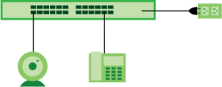
To view the current amount of power that PDs are receiving from the Switch, click PORT > PoE Setup > PoE Status.
The following table describes the labels in this screen.
label | description |
|---|---|
PoE Mode | This field displays the power management mode used by the Switch, whether it is in Classification or Consumption mode. |
Total Power (W) | This field displays the total power the Switch can provide to the connected PoE-enabled devices on the PoE ports. |
PoE Usage (%) | This field displays the amount of power currently being supplied to connected PoE devices (PDs) as a percentage of the total PoE power the Switch can supply. When PoE usage reaches 100%, the Switch will shut down PDs one-by-one according to the PD priority which you configured in PORT > PoE Setup > PoE Setup. |
Consuming Power (W) | This field displays the amount of power the Switch is currently supplying to the connected PoE-enabled devices. |
Allocated Power (W) | This field displays the total amount of power the Switch (in classification mode) has reserved for PoE after negotiating with the connected PoE devices. It shows NA when the Switch is in consumption mode. Consuming Power (W) can be less than or equal but not more than the Allocated Power (W). |
Remaining Power (W) | This field displays the amount of power the Switch can still provide for PoE. |
Port | This is the port index number. |
State | This field shows which ports can receive power from the Switch. • Disable – The PD connected to this port cannot get power supply. • Enable – The PD connected to this port can receive power. |
Class | This shows the power classification of the PD. Each PD has a specified maximum power that fall under one of the classes. The Class is a number from 0 to 6, where each value represents the range of power that the Switch provides to the PD. Each class corresponds to a default maximum power that can be extended in Port > PoE Setup > PoE Setup to the following values. • Class 0 – default: 0.44 W to 15.4 W. • Class 1 – default: 0.44 W to 4 W. • Class 2 – default: 0.44 W to 7 W. • Class 3 – default: 0.44 W to 15.4 W. • Class 4 – default: 0.44 W to 30 W. • Class 5 – default: 0.45 W to 45 W. • Class 6 – default: 0.45 W to 60 W. • Class 7 – default: 0.468 W to 75 W. • Class 8 – default: 0.468 W to 90 W. |
Priority | When the total power requested by the PDs exceeds the total PoE power budget on the Switch, you can set the PD priority to allow the Switch to provide power to ports with higher priority first. • Critical has the highest priority. • High has the Switch assign power to the port after all critical priority ports are served. • Low has the Switch assign power to the port after all critical and high priority ports are served. |
Power-Up | This field displays the PoE setting the Switch uses to provide power on this port. |
Consuming Power (W) | This field displays the current amount of power consumed by the PD from the Switch on this port. |
Max Power (W) | This field displays the maximum amount of power the PD could use from the Switch on this port. |
PoE Setup
Use this screen to set the PoE power management mode, priority levels, power-up mode and the maximum amount of power for the connected PDs.
The following table describes the labels in this screen.
label | description |
|---|---|
PoE Mode | Select the power management mode you want the Switch to use. • Classification – Select this if you want the Switch to reserve the maximum power for each PD according to the PD’s power class and priority level. If the total power supply runs out, PDs with lower priority do not get power to function. In this mode, the maximum power is reserved based on what you configure in Max Power or the standard power limit for each class. • Consumption – Select this if you want the Switch to supply the actual power that the PD needs. The Switch also allocates power based on a port’s Max Power and the PD’s power class and priority level. The Switch puts a limit on the maximum amount of power the PD can request and use. In this mode, the default maximum power that can be delivered to the PD is 33 W (IEEE 802.3at Class 4) or 22 W (IEEE 802.3af Classes 0 to 3). |
Total Power (W) | By default, this field displays the total power the Switch can provide to the connected PoE-enabled devices on the PoE ports • XMG2230-28HP: 700 W (default). Enter a number ranging from 1 to 1440 W to set the maximum PoE power the PD(s) could use from this Switch. • XMG2230-52HP: 960 W (default). Enter a number ranging from 1 to 2400 W to set the maximum PoE power the PD(s) could use from this Switch. |
Port | This is the port index number. |
* | Settings in this row apply to all ports. Use this row only if you want to make some settings the same for all ports. Use this row first to set the common settings and then make adjustments on a port-by-port basis. Changes in this row are copied to all the ports as soon as you make them. |
Active | Select this to provide power to a PD connected to the port. If left unchecked, the PD connected to the port cannot receive power from the Switch. |
Priority | When the total power requested by the PDs exceeds the total PoE power budget on the Switch, you can set the PD priority to allow the Switch to provide power to ports with higher priority. Select Critical to give the highest PD priority on the port. Select High to set the Switch to assign the remaining power to the port after all critical priority ports are served. Select Low to set the Switch to assign the remaining power to the port after all critical and high priority ports are served. |
Power-Up | Set how the Switch provides power to a connected PD at power-up. Standard – the Switch follows the IEEE 802.3 Power over Ethernet standard to supply power to the connected PDs during power-up. Compatible – the Switch provides PD with power on the port without performing PoE classification. Select this if the connected PD does not comply with any PoE standard. • Click Reset on the Action field of the port supplying PoE power to the connected PD in PORT > PoE Setup > PoE Status, or • Disconnect and reconnect the Ethernet cable supplying PoE power from the port to the connected PD. |
Max Power (mW) | Specify the maximum amount of power the PD could use from the Switch on this port. If you leave this field blank, the Switch refers to the standard or default maximum power for each class. |
LLDP Power Via MDI | Select this to have the Switch negotiate PoE power with the PD connected to the port by transmitting LLDP Power Via MDI TLV frames. This helps the Switch allocate less power to the PD on this port. The connected PD must be able to request PoE power through LLDP. The Power Via MDI TLV allows PoE devices to advertise and discover the MDI power support capabilities of the sending port on the remote device. • Port Class • MDI Supported • MDI Enabled • Pair Controllable • PSE Power Pairs • Power Class |
Apply | Click Apply to save your changes to the Switch’s run-time memory. The Switch loses these changes if it is turned off or loses power, so use the Save link on the top navigation panel to save your changes to the non-volatile memory when you are done configuring. |
Cancel | Click Cancel to begin configuring this screen afresh. |
Port Setup
Use this screen to configure Switch port settings.
The following table describes the labels in this screen.
label | description |
|---|---|
Port | This is the port index number. |
* | Settings in this row apply to all ports. Use this row only if you want to make some settings the same for all ports. Use this row first to set the common settings and then make adjustments on a port-by-port basis. |
Active | Select this checkbox to enable a port. The factory default for all ports is enabled. A port must be enabled for data transmission to occur. |
Name | Type a descriptive name that identifies this port. You can enter up to 128 printable ASCII characters except [ ? ], [ | ], [ ' ], or [ " ]. |
Speed/Duplex | Select the speed and the duplex mode of the connection on this port. For an Ethernet port, the choices are Auto, Auto-1G, 10-an (10M/auto-negotiation), 10M / Full Duplex, 100-an (100M/auto-negotiation), 2.5G / Full Duplex, 5G / Full Duplex, and 100M / Full Duplex for a 100Base-T connection. 1G / Full Duplex is supported by both 1000Base-T and 1000Base-X connections. 10G / Full Duplex is supported by the 10 Gigabit Ethernet connections on the Switch that has a 10 Gigabit interface. For an SFP+ interface, the choices are Auto, Auto-1G, 1G / Full Duplex, and 10G / Full Duplex. Selecting Auto-1G or Auto (auto-negotiation) allows one port to negotiate with a peer port automatically to obtain the connection speed and duplex mode that both ends support. When auto-negotiation is turned on, a port on the Switch negotiates with the peer automatically to determine the connection speed and duplex mode. If the peer port does not support auto-negotiation or turns off this feature, the Switch determines the connection speed by detecting the signal on the cable and using half duplex mode. When the Switch’s auto-negotiation is turned off, a port uses the pre-configured speed and duplex mode when making a connection, therefore requiring you to make sure that the settings of the peer port are the same in order to connect. |
Flow Control | A concentration of traffic on a port decreases port bandwidth and overflows buffer memory causing packet discards and frame losses. Flow Control is used to regulate transmission of signals to match the bandwidth of the receiving port. The Switch uses IEEE 802.3x flow control in full duplex mode. IEEE 802.3x flow control is used in full duplex mode to send a pause signal to the sending port, causing it to temporarily stop sending signals when the receiving port memory buffers fill. Select Tx Rx to allow the Switch port to send pause signal to the connected device, and for the connected device to send a pause signal to the Switch. The Switch will temporarily stop sending signals after receiving pause signal. Select Tx to allow the Switch port to send pause signal to the connected device. Select Rx to allow the connected device to send a pause signal to the Switch. The Switch will temporarily stop sending signals. Otherwise, select Disable. |
802.1p Priority | This priority value is added to incoming frames without a (802.1p) tag. |
BPDU Ctrl | Configure the way to treat BPDUs received on this port. You must activate Bridging Control Protocol Transparency in the SYSTEM > Switch Setup screen first. Select Peer to process any BPDU (Bridge Protocol Data Units) received on this port. Select Tunnel to forward BPDUs received on this port. Select Discard to drop any BPDU received on this port. Select Network to process a BPDU with no VLAN tag and forward a tagged BPDU. |
Media Type | You can insert either an SFP+ transceiver or an SFP+ Direct Attach Copper (DAC) cable into the 10 Gigabit interface of the Switch. Select the media type (Auto / SFP+ / DAC10G) of the SFP+ module that is attached to the 10 Gigabit interface. The default setting is Auto. When Auto is selected, the Switch chooses SFP+ or DAC10G mode based on the DDMI information. |
Apply | Click Apply to save your changes to the Switch’s run-time memory. The Switch loses these changes if it is turned off or loses power, so use the Save link on the top navigation panel to save your changes to the non-volatile memory when you are done configuring. |
Cancel | Click Cancel to begin configuring this screen afresh. |