Hardware
See the Quick Start Guide for hardware installation and connections.
Ports
This section shows the ports and buttons on the following models:
• Root
Root Plus
Place the Root Plus with the grooved surface facing upward. The Root Plus is square. Position it so that the edge with the four ports is closest to you.
Root Plus Ports and Buttons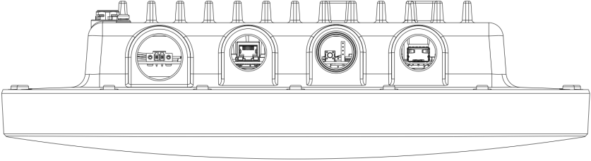
Root Plus Ports and Buttons with I/O labels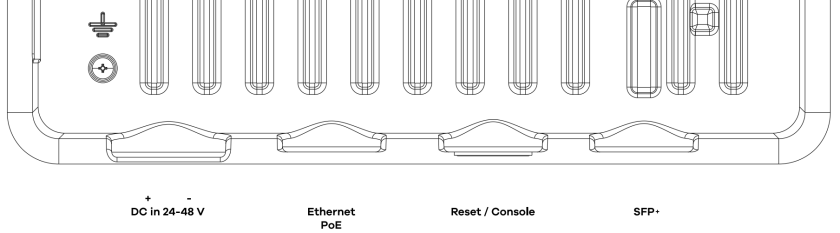
The following are the items on the ports panels from left to right.
label | description |
|---|---|
DC in 24–48 V | Connect the power to start the Root (Plus). See DC Power Connection for more information on connecting the DC power to the Root (Plus). |
Ethernet PoE (IEEE 802.3bt 60 W standard) | Connect the Root (Plus) to the PoE injector’s power port to power the Root (Plus). Then connect a router or computer to the PoE injector’s LAN port to connect the Root (Plus) to the backbone of your network. |
Reset / Console | Press the button for more than 5 seconds to return the Root (Plus) to the factory defaults. You can use the 4-pin console port to manage the Root (Plus) using CLI commands. You will be prompted to enter your user name and password. See the Command Reference Guide for more information about the CLI. When configuring using the console port, you need a computer equipped with communications software configured to the following parameters: • Speed 115200 bps • Data Bits 8 • Parity None • Stop Bit 1 • Flow Control Off |
SFP+ | Use an SFP+ transceiver in this port for high-bandwidth backbone connections. |
Root
Locate the mounting handle on the back of the Root. Remove the cover below the handle to access the PoE port inside. Place the Root with the mounting handle facing upward and the port facing toward you.
Root Port and Button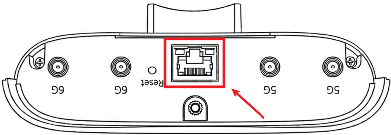
The following are the items on the ports panels for your Root.
label | description |
|---|---|
PoE | Connect the PoE port to provide power and network access to the Root (Plus). |
Reset | Press the button for more than 5 seconds to return the Root (Plus) to the factory defaults. |
The Root has four RP-SMA female antenna connectors for external antennas: two for the 5 GHz band and two for the 6 GHz band. Connect all four antennas to the Root before use.
 External antennas are not included and must be purchased separately. Zyxel recommends the ACCESSORY-ZZ0114F antenna. Customers may also use other compatible antennas that meet the required frequency bands and applicable regulatory requirements.
The Zyxel ACCESSORY-ZZ0114F antenna specifications are shown in the following table for your reference.
label | Specification | |||
|---|---|---|---|---|
Antenna | 5G-1 | 5G-2 | 6G-1 | 6G-2 |
Connector | RP-SMA male | RP-SMA male | RP-SMA male | RP-SMA male |
Polarization | -45 | +45 | -45 | +45 |
Frequency | 5150 to 5850 | 5150 to 5850 | 5925 to 7125 | 5925 to 7125 |
Peak Gain (dBi) | 12.5 | 12.1 | 12.9 | 12.9 |
Voltage Standing Wave Ratio (VSWR) | < 2.5 | < 3 | ||
Half-Power Beamwidth (HPBW)-Azimuth | 19.2 to 23.3⁰ | 16.8 to 24.1⁰ | 17.2 to 26.9⁰ | 17.2 to 25.7⁰ |
Half-Power Beamwidth (HPBW)-Elevation | 14.3 to 21.8⁰ | 15.7 to 19.2⁰ | 12.9 to 16.1⁰ | 12.0 to 16.8⁰ |
Isolation (dB) | 17 | 17 | ||
Cross Isolation (dB) | 25 | |||
Power (Watts) | 5 | |||
Impedance (Ohms) | 50 | |||
Type | Patch |
PoE
Power Over Ethernet (PoE) is a technology that allows Ethernet cables to supply power and transmit data simultaneously through a single Ethernet cable.
The following figure shows a PoE injector supplying power to the Root Plus from a power outlet, and connecting it to the local network through a router, or gateway.
Root Plus’s PoE Application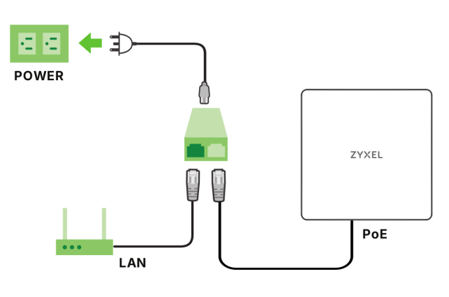
To view the Root (Plus)’s supported PoE standards, see Feature Comparison. Use Ethernet cables that correspond to the PoE standard your Root (Plus) supports (see Root (Plus) PoE Standards).
The supported PoE standards for Root (Plus) are:
• IEEE 802.3af Power over Ethernet (PoE)
• IEEE 802.3at Power over Ethernet + (PoE+)
• IEEE 802.3bt Power over Ethernet ++ (PoE++)
The following table describes the PoE standards.
PoE FEATURES | PoE | PoE+ | PoE++ |
|---|---|---|---|
IEEE Standard | IEEE 802.3af | IEEE 802.3at | IEEE 802.3bt |
Supported Models | Root | Root Plus, Root | Root Plus |
PoE Type | Type 1 | Type 2 | Type 3 |
PSE Port Power | PSE Port Power | PSE Port Power | PSE Port Power |
IEEE Power Classification | Class 0, 1, 2, 3 | Class 4 | Class 5, 6 |
Maximum Power Per Port | 15.4 W | 30 W | 60 W |
Port Voltage Range | 44 – 57 V | 50 – 57 V | 50 – 57 V |
Cables | Cables | Cables | Cables |
Twisted Pairs Used | 2-pair | 2-pair | 4-pair |
Supported Cables | Cat3 or better | Cat5 or better | Cat5 or better |
DC Power Connection
The Root Plus uses a single D-sub series terminal block plug with two pins. Use two wires to connect to the terminal block: one for the positive terminal and one for the negative terminal.
The current rating of the power wires must be greater than 16 AWG. The power supply to which the Root Plus connects must have a built-in circuit breaker or switch to toggle the power. When installing the Root Plus power wire, push the wire firmly into the terminal as deep as possible and make sure that no exposed (bare) wire can be seen or touched. Exposed power wire is dangerous. Use extreme care when connecting a DC power source to the Root Plus.
WARNING! Working with high-voltage DC power is dangerous. To ensure safety of equipment and regulatory compliance, the DC power connection must be performed by a certified technician.
To connect a power supply:
1 Use a screwdriver to loosen the captive screws on the D-sub's terminal block.
2 Connect one end of a power wire to the Root Plus’s 48 V (return) pin and tighten the captive screw.
3 Connect the other end of the power wire to the positive terminal on the DC power supply.
4 Connect one end of a power wire to the Root Plus’s –48 V (input) pin and tighten the captive screw.
5 Connect the other end of the power wire to the negative terminal on the power supply.
6 Insert the D-sub terminal block’s male connector plug into the Root Plus’s DC in 24–48 V port and tighten the two captive screws.
SFP+ Slot
This is the slot for SFP+ (Small Form-Factor Pluggable) transceivers. A transceiver is a single unit that houses a transmitter and a receiver. The Root Plus does not come with a transceiver. You must use a transceiver that comply with the Small Form-factor Pluggable (SFP+) Transceiver MultiSource Agreement (MSA). See the SFF committee’s specifications.
You can change a transceiver while the Root Plus is operating. You can use a different transceiver to connect to devices with different types of fiber optic or even copper cable connectors.
WARNING! To avoid possible eye injury, do not look into an operating fiber optic module’s connectors.
HANDLING! All transceivers are static sensitive. To prevent damage from electrostatic discharge (ESD), it is recommended you attach an ESD preventive wrist strap to your wrist and to a bare metal surface when you install or remove a transceiver.
STORAGE! All modules are dust sensitive. When not in use, always keep the dust plug on. Avoid getting dust and other contaminant into the optical bores, as the optics do not work correctly when obstructed with dust.
HANDLING! All transceivers are static sensitive. To prevent damage from electrostatic discharge (ESD), it is recommended you attach an ESD preventive wrist strap to your wrist and to a bare metal surface when you install or remove a transceiver.
STORAGE! All modules are dust sensitive. When not in use, always keep the dust plug on. Avoid getting dust and other contaminant into the optical bores, as the optics do not work correctly when obstructed with dust.
Transceiver Installation
Use the following steps to install a transceiver.
1 Attach an ESD preventive wrist strap to your wrist and to a bare metal surface.
2 Align the transceiver in front of the slot opening.
3 Make sure the latch is in the lock position (latch styles vary), then insert the transceiver into the slot with the exposed section of PCB board facing down.
4 Press the transceiver firmly until it clicks into place.
5 The Root Plus automatically detects the installed transceiver.
6 Remove the dust plugs from the transceiver and cables (dust plug styles vary).
7 Identify the signal transmission direction of the fiber optic cables and the transceiver. Insert the fiber optic cable into the transceiver.
Latch in the Lock Position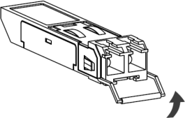
Transceiver Installation Example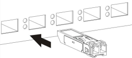
Connecting the Fiber Optic Cables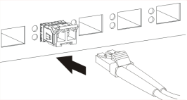
Transceiver Removal
Use the following steps to remove an SFP transceiver.
1 Attach an ESD preventive wrist strap to your wrist and to a bare metal surface on the chassis.
2 Remove the fiber optic cables from the transceiver.
3 Pull out the latch and down to unlock the transceiver (latch styles vary).
Make sure the transceiver’s latch is pushed all the way down, so the transceiver can be pulled out successfully.4 Pull the latch, or use your thumb and index finger to grasp the tabs on both sides of the transceiver, and carefully slide it out of the slot.
Do NOT pull the transceiver out by force. You could damage it. If the transceiver will not slide out, grasp the tabs on both sides of the transceiver with a slight up or down motion and carefully slide it out of the slot. If unsuccessful, contact Zyxel Support to prevent damage to your Root Plus and transceiver.5 Insert the dust plug into the ports on the transceiver and the cables.
Removing the Fiber Optic Cables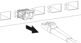
Opening the Transceiver’s Latch Example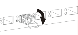
Transceiver Removal Example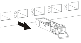
Grounding
Earth grounding helps protect against lightning and interference.
The power installation must be performed by qualified service personnel and should conform to the National Electrical Code.The Root Plus must be connected to earth ground to adequately ground the Root Plus and protect the operator from electrical hazards.
Qualified service personnel must confirm that the protective earthing terminal of the building is a valid terminal.
Before connecting the ground, ensure that a qualified service personnel has attached an appropriate ground lug to the ground cable.
1 Locate the ground screw on the rear panel of Root Plus. Place the device with the grooved surface facing upward and the edge with the four ports is closest to you. Feel for the engraved grounding symbol at the bottom-left corner of the grooved surface. The ground screw is directly below it.
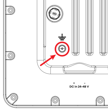
2 Remove the ground screw.
3 Secure a green/yellow ground cable (18 AWG or smaller) to the Root Plus’s rear panel using the ground screw.
4 Attach the other end of the cable to the ground, either to the same ground electrode as the pole you installed the Root Plus on or to the main grounding electrode of the building.
Follow your country's regulations and safety instructions to electrically ground the Root Plus properly. If you are uncertain that suitable grounding is available, contact the appropriate electrical inspection authority or an electrician.Warning! Connect the ground cable before you connect any other cables or wiring.
The figure below illustrates how the ground cable (A) is attached to the Root Plus and goes to the earth ground (B).
Grounding Example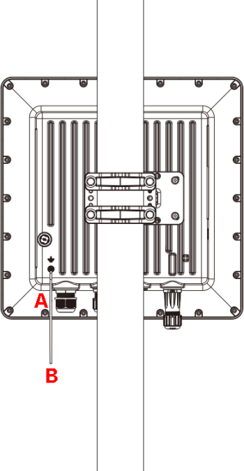
The Root Plus should be installed at a 90-degree angle perpendicular to the ground.
Root (Plus) LED
This section shows the LED behavior of the following models:
• Root
For a complete description and simulation of LED behavior, see the LED Simulator.
Root Plus
Place the Root Plus with the grooved surface facing you and the edge with the four ports at the bottom. The Status LED is located on the right side panel.
Root Plus Status LED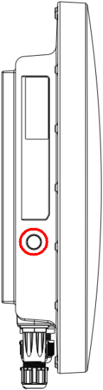
The following are the LED descriptions for your Root Plus.
Color | status | description | |
|---|---|---|---|
 | Amber | Blinks between amber and green alternately (300 milliseconds interval). | The Root Plus is booting up. |
Green | |||
 | Green | Blinking (On for 300 milliseconds, Off for 300 milliseconds) | The Root Plus is connected to NCC and registered, but no WiFi clients are connected to the Root Plus. |
 | Green | Steady On | The Root Plus is ready for use. OR The Root Plus is connected to NCC and registered, with WiFi clients connected to the Root Plus. |
 | Amber | Steady On | The Root Plus is not connected to NCC, but WiFi clients are connected to the Root Plus. |
 | Amber | Blinking (On for 300 milliseconds, Off for 300 milliseconds) | The Root Plus is not connected to NCC, and no WiFi clients are connected to the Root Plus. |
 | Bright Blue | Steady On | The Root Plus has completed the boot up process. |
 | Blue | Blinking (On for 1 second, Off for 1 second) | The Root Plus is performing a Channel Availability Check (CAC) with Dynamic Frequency Selection (DFS) to avoid radar channel interference. |
 | Red | Steady On | The Root Plus failed to complete the boot up process. |
 | Red | Fast Blinking (On for 50 milliseconds, Off for 50 milliseconds) | The Root Plus is undergoing firmware upgrade. |
 | Red | Blinking (On for 1 second, Off for 1 second) | The Root Plus WiFi is disabled or has failed. |
| Red | Slow Blinking (On for 1 second, Off for 5 seconds) | The Root Plus is connected to NCC, but not registered with NCC. |
Root
Locate the mounting handle on the upper rear of the Root. The LED is located on the lower front of the Root.
Root LED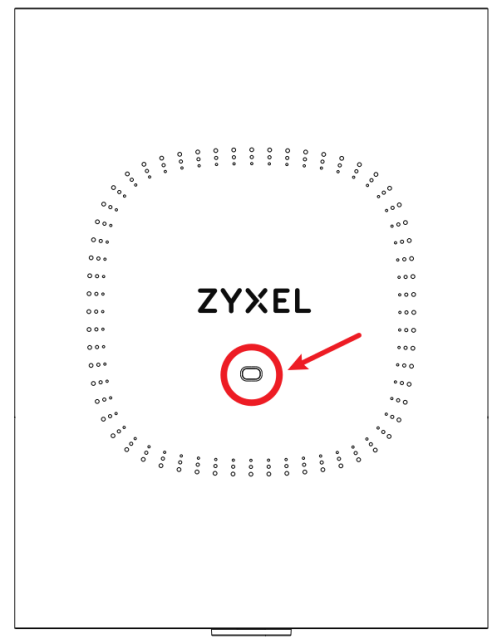
The following are the LED descriptions for your Root.
Color | status | description | |
|---|---|---|---|
| Amber | Blinks between amber and green alternately (300 milliseconds interval). | The Root is booting up. |
Green | |||
| Green | Blinking (On for 300 milliseconds, Off for 300 milliseconds) | The Root is connected to NCC and registered, but no WiFi clients are connected to the Root. |
| Green | Steady On | The Root is ready for use. OR The Root is connected to NCC and registered, with WiFi clients connected to the Root. |
| Amber | Steady On | The Root is not connected to NCC, but WiFi clients are connected to the Root. |
| Amber | Blinking (On for 300 milliseconds, Off for 300 milliseconds) | The Root is not connected to NCC, and no WiFi clients are connected to the Root. |
| Bright Blue | Steady On | The Root has completed the boot up process. |
| Blue | Blinking (On for 1 second, Off for 1 second) | The Root is performing a Channel Availability Check (CAC) with Dynamic Frequency Selection (DFS) to avoid radar channel interference. |
| Red | Steady On | The Root failed to complete the boot up process. |
| Red | Fast Blinking (On for 50 milliseconds, Off for 50 milliseconds) | The Root is undergoing firmware upgrade. |
| Red | Blinking (On for 1 second, Off for 1 second) | The Root WiFi is disabled or has failed. |
| Red | Slow Blinking (On for 1 second, Off for 5 seconds) | The Root is connected to NCC, but not registered with NCC. |
Resetting the Root (Plus)
This section shows the location of Root (Plus)’s Reset buttons and how to reset the device.
Root Plus Reset Button
Place the Root Plus with the grooved surface facing upward and the edge with the four ports closest to you. The Reset button is the third opening from the left.
Root Plus’s Reset Button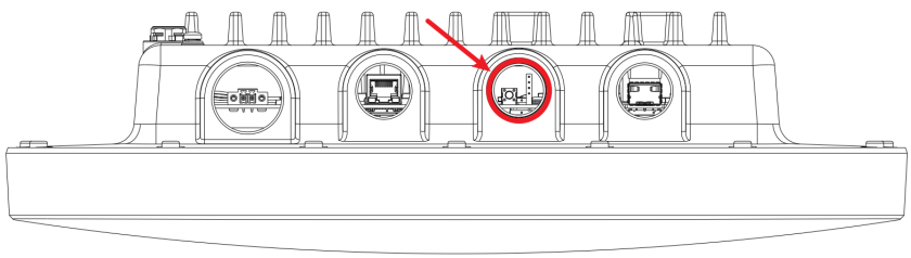
Root Reset Button
Place the Root with the mounting handle facing upward and the port facing toward you. The Reset button is located to the left of the PoE port. Use a pin to press it.
Root’s Reset Button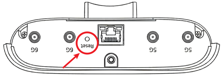
If you cannot access the Root (Plus) by any method, try restarting it by turning the power off and then on again. If you still cannot access the Root (Plus) by any method or you forget the administrator password(s), you can reset the Root (Plus) to its factory-default settings. Any configuration files or shell scripts that you saved on the Root (Plus) should still be available afterwards.
Use the following procedure to reset the Root (Plus) to its factory-default settings. This overwrites the settings in the startup-config.conf file with the settings in the system-default.conf file.
This procedure removes the current configuration.1 Make sure the Power LED is on and not blinking.
2 Press and hold the Reset button until the Power LED begins to blink. (This usually takes about ten seconds.)
3 Release the Reset button, and wait for the Root (Plus) to restart.
You should be able to access the Root (Plus) using the local GUI’s default settings.