Wireless
Overview
The following figure provides an example of a WiFi network.
Example of a WiFi Network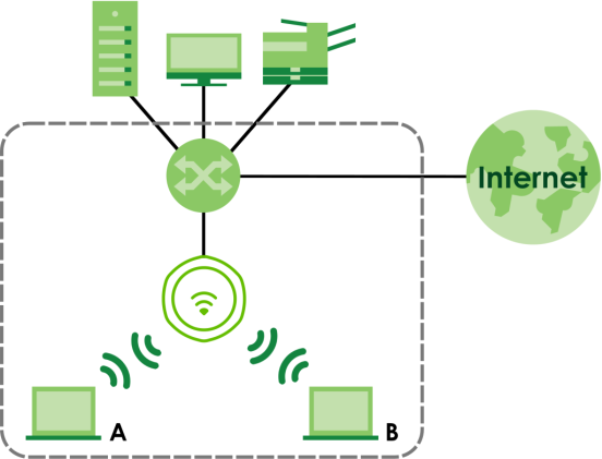
Station / WiFi Client
A station or WiFi client is any WiFi-capable device that can connect to an AP using a WiFi signal.
Dynamic Channel Selection (DCS)
Dynamic Channel Selection (DCS) is a feature that allows an AP to automatically select the radio channel which it broadcasts. For more information, see Technical Reference.
Load Balancing (Wireless)
Wireless load balancing is the process where you limit the number of connections allowed on an wireless access point (AP) or you limit the amount of wireless traffic transmitted and received on it so the AP does not become overloaded.
AP Management
Use this screen to manage the Zyxel Device’s general WiFi settings.
Each field is described in the following table.
Label | Description |
|---|---|
Radio 1 Setting | |
Radio 1 Activate | Select the checkbox to enable the Zyxel Device’s first (default) radio. |
Radio 1 OP Mode | Select the operating mode for radio 1. AP Mode means the radio can receive connections from WiFi clients and pass their data traffic through to the Zyxel Device to be managed (or subsequently passed on to an upstream gateway for managing). Root AP means the radio acts as an AP and also supports the wireless connections with other APs (in repeater mode) to form a WDS (Wireless Distribution System) to extend its wireless network. Repeater means the radio can establish a wireless connection with other APs (in either root AP or repeater mode) to form a WDS. |
Radio 1 Profile | Select the radio profile the radio uses. |
Add  | This button is not available after you configure the Zyxel Device using the wizard. Click the Add icon (  )to open a screen where you can create a new entry. For features where the entry’s position in the numbered list is important (features where the Zyxel Device applies the table’s entries in order like the SSID for example), you can select an entry and click Add to create a new entry after the selected entry. )to open a screen where you can create a new entry. For features where the entry’s position in the numbered list is important (features where the Zyxel Device applies the table’s entries in order like the SSID for example), you can select an entry and click Add to create a new entry after the selected entry. |
Radio 1 WDS Profile | This field is available only when the radio is in Root AP or Repeater mode. Select the WDS profile the radio uses to connect to a root AP or repeater. |
Enable WDS Wireless Bridging | Not all models support this feature. See Zyxel Device Product Feature Comparison for models that support wireless bridge. If you set the Zyxel Device as a root AP, the radio that’s bridging with the Zyxel Device should be in repeater mode. Be careful to avoid bridge loops. For example, if your root AP and the Zyxel Device are connected to a switch, and they’re also connected to each other using a WiFi connection. This will create bridge loops. This field is available only when the radio is in Repeater mode. Select this to enable WDS wireless bridging on the Zyxel Device to establish wireless links with other APs. See Zyxel Device Roles for more information on Wireless Distribution System (WDS). |
Uplink Selection Mode | This field is available only when the radio is in Repeater mode. Select AUTO to have the Zyxel Device automatically use the settings in the applied WDS profile to connect to a root AP or repeater. Select Manual to have the Zyxel Device connect to the root AP or repeater with the MAC address specified in the Radio 1 Uplink MAC Address field. |
Setup Wireless Bridge Vlan ID | This appears if you select Enable WDS Wireless Bridging. Click this to show the Wireless Bridge Vlan Setting pop-up window. This link is available only when the radio is in Root AP or Repeater mode. |
Wireless Bridge Vlan Setting | |
Add | Click this to add an entry in the table. |
Remove | Select an entry and click this to remove the selected entry. |
# | This field is a sequential value. It is not associated with any VLAN ID. |
Wireless Bridge Vlan ID | Enter a VLAN ID for the wireless bridge. The VLAN IDs you set on your root AP should be the same as the VLAN ID you set here. See Zyxel Device Roles for more information on wireless bridge. |
OK | Click OK to save your changes back to the Zyxel Device. |
Close | Click Close to close the pop-up window without saving your changes. |
Max Output Power | Enter the maximum output power (between 0 to 30 dBm) of the Zyxel Device in this field. If there is a high density of APs in an area, decrease the output power of the Zyxel Device to reduce interference with other APs. |
MBSSID Settings | |
Edit  | Click the Edit icon (  )to open a screen where you can modify the entry’s settings. In some tables you can just click a table entry and edit it directly in the table. For those types of tables small red triangles display for table entries with changes that you have not yet applied. )to open a screen where you can modify the entry’s settings. In some tables you can just click a table entry and edit it directly in the table. For those types of tables small red triangles display for table entries with changes that you have not yet applied. |
# | This field shows the index number of the SSID |
SSID Profile | This field displays the SSID profile that is associated with the radio profile. |
Band | This field displays the frequency bands to which the SSID profile is applicable. If the SSID profile is not applicable to the current radio, the SSID profile will not be enabled. You can configure the SSID profile’s applicable frequency bands in the Edit SSID Profile screen (click the Edit button next to the profile). |
Radio 2/3 Setting The Radio 3 Setting fields are only available for Zyxel Device models that support triple radios. | |
Radio 2/3 Activate | This displays if the Zyxel Device has a second radio. Select the checkbox to enable the Zyxel Device’s second radio. |
Radio 2/3 OP Mode | This displays if the Zyxel Device has a second radio. Select the operating mode for radio 2. AP Mode means the radio can receive connections from WiFi clients and pass their data traffic through to the Zyxel Device to be managed (or subsequently passed on to an upstream gateway for managing). Root AP means the radio acts as an AP and also supports the wireless connections with other APs (in repeater mode) to form a WDS to extend its wireless network. Repeater means the radio can establish a wireless connection with other APs (in either root AP or repeater mode) to form a WDS. |
Radio 2/3 Profile | This displays if the Zyxel Device has a second/third radio. Select the radio profile the radio uses. |
Radio 2/3 WDS Profile | This field is available only when the radio is in Root AP or Repeater mode. Select the WDS profile the radio uses to connect to a root AP or repeater. |
Add  | This button is not available after you configure the Zyxel Device using the wizard. Click the Add icon (  )to open a screen where you can create a new entry. For features where the entry’s position in the numbered list is important (features where the Zyxel Device applies the table’s entries in order like the SSID for example), you can select an entry and click Add to create a new entry after the selected entry. )to open a screen where you can create a new entry. For features where the entry’s position in the numbered list is important (features where the Zyxel Device applies the table’s entries in order like the SSID for example), you can select an entry and click Add to create a new entry after the selected entry. |
Enable WDS Wireless Bridging | Not all models support this feature. See Zyxel Device Product Feature Comparison for models that support wireless bridge. If you set the Zyxel Device as a root AP, the radio that’s bridging with the Zyxel Device should be in repeater mode. Be careful to avoid bridge loops. For example, if your root AP and the Zyxel Device are connected to a switch, and they’re also connected to each other using a WiFi connection. This will create bridge loops. This field is available only when the radio is in Repeater mode. Select this to enable WDS wireless bridging on the Zyxel Device to establish wireless links with other APs. See Zyxel Device Roles for more information on Wireless Distribution System (WDS). |
Uplink Selection Mode | This field is available only when the radio is in Repeater mode. Select AUTO to have the Zyxel Device automatically use the settings in the applied WDS profile to connect to a root AP or repeater. Select Manual to have the Zyxel Device connect to the root AP or repeater with the MAC address specified in the Radio 1 Uplink MAC Address field. |
Setup Wireless Bridge Vlan ID | Click this to show the Wireless Bridge Vlan Setting pop-up window. This link is available only when the radio is in Root AP or Repeater mode. |
Wireless Bridge Vlan Setting | |
Add | Click this to add an entry in the table. |
Remove | Select an entry and click this to remove the selected entry. |
# | This field is a sequential value. It is not associated with any VLAN ID. |
Wireless Bridge Vlan ID | Enter a VLAN ID for the wireless bridge. The VLAN IDs you set on your root AP should be the same as the VLAN ID you set here. See Zyxel Device Roles for more information on wireless bridge. |
OK | Click OK to save your changes back to the Zyxel Device. |
Close | Click Close to close the pop-up window without saving your changes. |
Max Output Power | Enter the maximum output power (between 0 to 30 dBm) of the Zyxel Device in this field. If there is a high density of APs in an area, decrease the output power of the Zyxel Device to reduce interference with other APs. |
MBSSID Settings | |
Edit  | Click Edit (  )to open a screen where you can modify the entry’s settings. In some tables you can just click a table entry and edit it directly in the table. For those types of tables small red triangles display for table entries with changes that you have not yet applied. )to open a screen where you can modify the entry’s settings. In some tables you can just click a table entry and edit it directly in the table. For those types of tables small red triangles display for table entries with changes that you have not yet applied. |
# | This field shows the index number of the SSID |
SSID Profile | This field shows the SSID profile that is associated with the radio profile. |
Band | This field displays the radio bands to which the SSID profile is applicable. If the SSID profile is not applicable to the current radio, the SSID profile will not be enabled. You can configure the SSID profile’s applicable radio bands in the Edit SSID Profile screen (click the Edit button next to the profile). |
Apply | Click Apply to save your changes back to the Zyxel Device. |
Reset | Click Reset to return the screen to its last-saved settings. |
Rogue AP
Use this screen to enable Rogue AP Detection and import/export a rogue or friendly AP list in a txt file.
Rogue APs
A rogue AP is a wireless access point operating in a network’s coverage area that is not under the control of the network administrator, and which can potentially open up holes in a network’s security.
In the following example, a corporate network’s security is compromised by a rogue AP (RG) set up by an employee at his workstation in order to allow him to connect his notebook computer wirelessly (A). The company’s legitimate WiFi network (the dashed ellipse B) is well-secured, but the rogue AP uses inferior security that is easily broken by an attacker (X) running readily available encryption-cracking software. In this example, the attacker now has access to the company network, including sensitive data stored on the file server (C).
Rogue AP Example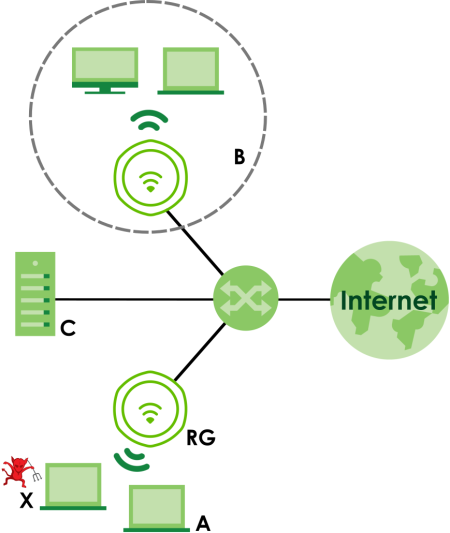
Friendly APs
If you have more than one AP in your WiFi network, you should also configure a list of “friendly” APs. Friendly APs are wireless access points that you know are not a threat. It is recommended that you export (save) your list of friendly APs often, especially if you have a network with a large number of access points. Exported lists show MAC addresses in txt file format separated by line breaks.
Rogue AP Detection
This feature allows the Zyxel Device to monitor the WiFi signals for other wireless APs (see also Radio Frequency (RF) Monitor). Detected APs will appear in the Monitor > Wireless > Detected Device screen, where the Zyxel Device will label APs with the criteria you select in Suspected Rogue AP Classification Rule as a suspected rogue. The APs which you mark as either rogue or friendly APs in the Monitor > Wireless > Detected Device screen will appear in the Wireless > Rogue AP screen. See Zyxel Device Product Feature Comparison to know which models support Rogue AP Detection.
Each field is described in the following table.
Label | Description |
|---|---|
Rogue AP Detection Setting | |
Enable Rogue AP Detection | Select this checkbox to detect Rogue APs in the network. |
Suspected Rogue AP Classification Rule | Select the checkboxes (Weak Security (Open, WEP, WPA-PSK), Hidden SSID, SSID Keyword) of the characteristics an AP should have for the Zyxel Device to mark it as a Rogue AP. |
Add | Click this to add an SSID Keyword. |
Edit | Select an SSID Keyword and click this button to modify it. |
Remove | Select an existing SSID keyword and click this button to delete it. |
# | This is the SSID Keyword’s index number in this list. |
SSID Keyword | This field displays the SSID Keyword. |
Rogue/Friendly AP List | |
Add | Click this button to add an AP to the list and assign it either friendly or rogue status. |
Edit | Select an AP in the list to edit and reassign its status. |
Remove | Select an AP in the list to remove. |
# | This field is a sequential value, and it is not associated with any interface. |
Role | This field indicates whether the selected AP is a rogue-ap or a friendly-ap. To change the AP’s role, click the Edit button. |
MAC Address | This field indicates the AP’s radio MAC address. |
Description | This field displays the AP’s description. You can modify this by clicking the Edit button. |
Rogue/Friendly AP List Importing/Exporting | These controls allow you to export the current list of rogue and friendly APs or import existing lists. |
File Path / Browse / Importing | Enter the file name and path of the list you want to import or click the Browse button to locate it. Once the File Path field has been populated, click Importing to bring the list into the Zyxel Device. You need to wait a while for the importing process to finish. |
Exporting | Click this button to export the current list of either rogue APs or friendly APS. |
Apply | Click Apply to save your changes back to the Zyxel Device. |
Reset | Click Reset to return the screen to its last-saved settings. |
Add/Edit Rogue/Friendly AP List
Each field is described in the following table.
Label | Description |
|---|---|
MAC | Enter the MAC address of the AP you want to add to the list. A MAC address is a unique hardware identifier in the following hexadecimal format: xx:xx:xx:xx:xx:xx where xx is a hexadecimal number separated by colons. |
Description | Enter up to 60 characters for the AP’s description. Spaces and underscores are allowed. |
Role | Select either Rogue AP or Friendly AP for the AP’s role. |
OK | Click OK to save your changes back to the Zyxel Device. |
Cancel | Click Cancel to close the window with changes unsaved. |
Load Balancing
Use this screen to configure wireless network traffic load balancing between the APs on your network (see Load Balancing ).
Each field is described in the following table.
Label | Description |
|---|---|
Enable Load Balancing | Select this to enable load balancing on the Zyxel Device. Use this section to configure wireless network traffic load balancing between the managed APs in this group. |
Mode | Select a mode by which load balancing is carried out. Select By Station Number to balance network traffic based on the number of specified stations connected to the Zyxel Device. Select By Traffic Level to balance network traffic based on the volume generated by the stations connected to the Zyxel Device. Select By Smart Classroom to balance network traffic based on the number of specified stations connected to the Zyxel Device. The Zyxel Device ignores association request and authentication request packets from any new station when the maximum number of stations is reached. If you select By Station Number or By Traffic Level, once the threshold is crossed (either the maximum station numbers or with network traffic), the Zyxel Device delays association request and authentication request packets from any new station that attempts to make a connection. This allows the station to automatically attempt to connect to another, less burdened AP if one is available. |
Max Station Number | Enter the threshold number of stations at which the Zyxel Device begins load balancing its connections. |
Traffic Level | Select the threshold traffic level at which the Zyxel Device begins load balancing its connections (Low, Medium, High). The maximum bandwidth allowed for each level is: • Low - 11 Mbps • Medium - 23 Mbps • High - 35 Mbps |
Disassociate station when overloaded | This function is enabled by default and the disassociation priority is always Signal Strength when you set Mode to By Smart Classroom. Select this option to disassociate WiFi clients connected to the AP when it becomes overloaded. If you do not enable this option, then the AP simply delays the connection until it can afford the bandwidth it requires, or it transfers the connection to another AP within its broadcast radius. The disassociation priority is determined automatically by the Zyxel Device and is as follows: • Idle Timeout - Devices that have been idle the longest will be kicked first. If none of the connected devices are idle, then the priority shifts to Signal Strength. • Signal Strength - Devices with the weakest signal strength will be kicked first. |
Apply | Click Apply to save your changes back to the Zyxel Device. |
Reset | Click Reset to return the screen to its last-saved settings. |
Disassociating and Delaying Connections
When your AP becomes overloaded, there are two basic responses it can take. The first one is to “delay” a client connection. This means that the AP withholds the connection until the data transfer throughput is lowered or the client connection is picked up by another AP. If the client is picked up by another AP then the original AP cannot resume the connection.
For example, here the AP has a balanced bandwidth allotment of 6 Mbps. If laptop R connects and it pushes the AP over its allotment, say to 7 Mbps, then the AP delays the red laptop’s connection until it can afford the bandwidth or the laptop is picked up by a different AP with bandwidth to spare.
Delaying a Connection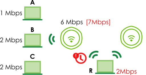
The second response your AP can take is to disassociate with clients that are pushing it over its balanced bandwidth allotment.
Disassociating with a Client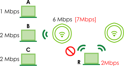
Connections are cut based on either idle timeout or signal strength. The Zyxel Device first looks to see which devices have been idle the longest, then starts kicking them in order of highest idle time. If no connections are idle, the next criteria the Zyxel Device analyzes is signal strength. Devices with the weakest signal strength are kicked first.
DCS
Use this screen to configure dynamic radio channel selection (see Dynamic Channel Selection (DCS) ).
Each field is described in the following table.
Label | Description |
|---|---|
DCS Now | Click this to have the Zyxel Device scan for and select an available channel immediately. |
Apply | Click Apply to save your changes back to the Zyxel Device. |
Reset | Click Reset to return the screen to its last-saved settings. |
Technical Reference
The following section contains additional technical information about the features described in this chapter.
Dynamic Channel Selection
When numerous APs broadcast within a given area, they introduce the possibility of heightened radio interference, especially if some or all of them are broadcasting on the same radio channel. If the interference becomes too great, then the network administrator must open his AP configuration options and manually change the channel to one that no other AP is using (or at least a channel that has a lower level of interference) in order to give the connected stations a minimum degree of interference. Dynamic channel selection frees the network administrator from this task by letting the AP do it automatically. The AP can scan the area around it looking for the channel with the least amount of interference.
In the 2.4 GHz spectrum, each channel from 1 to 13 is broken up into discrete 22 MHz segments that are spaced 5 MHz apart. Channel 1 is centered on 2.412 GHz while channel 13 is centered on 2.472 GHz.
An Example Three-Channel Deployment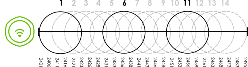
Three channels are situated in such a way as to create almost no interference with one another if used exclusively: 1, 6 and 11. When an AP broadcasts on any of these 3 channels, it should not interfere with neighboring APs as long as they are also limited to same trio.
An Example Four-Channel Deployment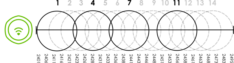
However, some regions require the use of other channels and often use a safety scheme with the following four channels: 1, 4, 7 and 11. While they are situated sufficiently close to both each other and the three so-called “safe” channels (1,6 and 11) that interference becomes inevitable, the severity of it is dependent upon other factors: proximity to the affected AP, signal strength, activity, and so on.
Finally, there is an alternative four channel scheme for ETSI, consisting of channels 1, 5, 9, 13. This offers significantly less overlap that the other one.
An Alternative Four-Channel Deployment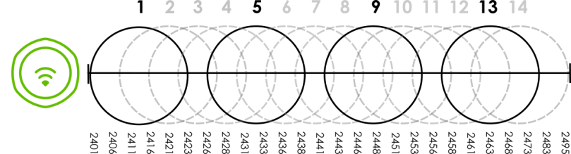
Load Balancing
Because there is a hard upper limit on an AP’s wireless bandwidth, load balancing can be crucial in areas crowded with wireless users. Rather than let every user connect and subsequently dilute the available bandwidth to the point where each connecting device receives a meager trickle, the load balanced AP instead limits the incoming connections as a means to maintain bandwidth integrity.
There are three kinds of wireless load balancing available on the Zyxel Device:
Load balancing by station number limits the number of devices allowed to connect to your AP. If you know exactly how many stations you want to let connect, choose this option.
For example, if your company’s graphic design team has their own AP and they have 10 computers, you can load balance for 10. Later, if someone from the sales department visits the graphic design team’s offices for a meeting and he tries to access the network, his computer’s connection is delayed, giving it the opportunity to connect to a different, neighboring AP. If he still connects to the AP regardless of the delay, then the AP may boot other people who are already connected in order to associate with the new connection.
Load balancing by smart classroom also limits the number of devices allowed to connect to your AP. But any new connections will be just rejected when the AP is overloaded.
Load balancing by traffic level limits the number of connections to the AP based on maximum bandwidth available. If you are uncertain as to the exact number of wireless connections you will have then choose this option. By setting a maximum bandwidth cap, you allow any number of devices to connect as long as their total bandwidth usage does not exceed the configured bandwidth cap associated with this setting. Once the cap is hit, any new connections are rejected or delayed provided that there are other APs in range.
Imagine a coffee shop in a crowded business district that offers free wireless connectivity to its customers. The coffee shop owner can’t possibly know how many connections his AP will have at any given moment. As such, he decides to put a limit on the bandwidth that is available to his customers but not on the actual number of connections he allows. This means anyone can connect to his wireless network as long as the AP has the bandwidth to spare. If too many people connect and the AP hits its bandwidth cap then all new connections must basically wait for their turn or get shunted to the nearest identical AP.