Initial Setup Example
Overview
This chapter shows how to set up the Switch for an example network.
The following lists the configuration steps for the initial setup:
Configure Switch Management IP Address
If the Switch fails to obtain an IP address from a DHCP server, the Switch will use 192.168.1.1 as the management IP address. You can configure another IP address in a different subnet for management purposes. The following figure shows an example.
Getting Started: Management IP Address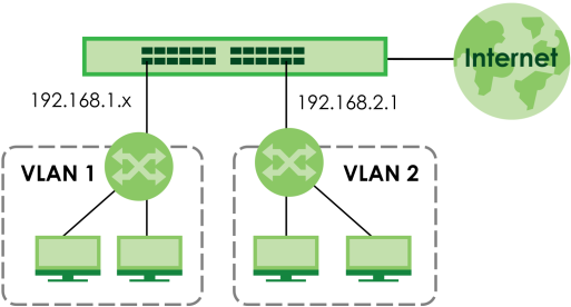
1 Connect your computer to any Ethernet port on the Switch. Make sure your computer is in the same subnet as the Switch.
2 Go to the SYSTEM > IP Setup > IP Setup screen. Click Add/Edit.
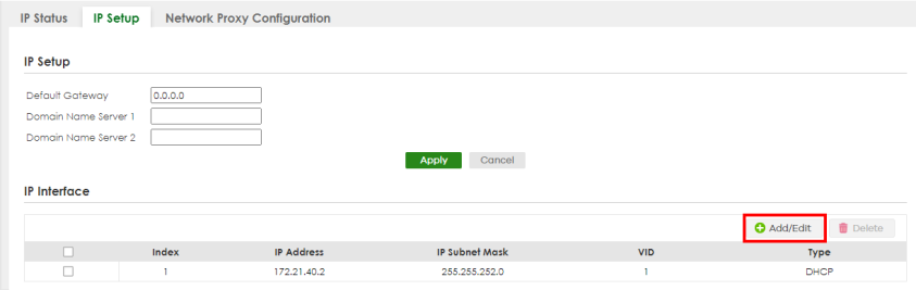
The following screen appears.
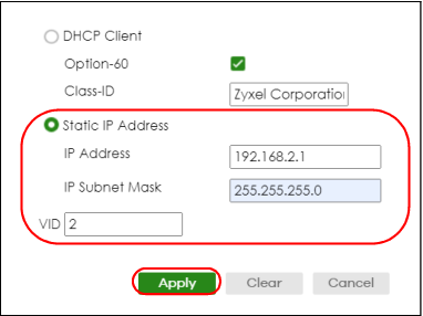
3 For the VLAN2 network, enter 192.168.2.1 as the IP address and 255.255.255.0 as the subnet mask.
4 In the VID field, enter the ID of the VLAN group to which you want this management IP address to belong. In this example, enter VLAN ID 2. This is the same as the VLAN ID you configure in the Static VLAN screen. See Create a VLAN for more information.
5 Click Apply to save your changes back to the run-time memory. Settings in the run-time memory are lost when the Switch’s power is turned off.
Change the Administrator Login Password
You can change the administrator login password regularly to ensure the security of your Switch. See Section 24.1 on page 189 for more information.
Create a VLAN
VLANs confine broadcast frames to the VLAN group in which the ports belongs. You can do this with port-based VLAN or tagged static VLAN with fixed port members.
In this example, you want to configure port 1 (P1) as a member of VLAN 2.
Getting Started: VLAN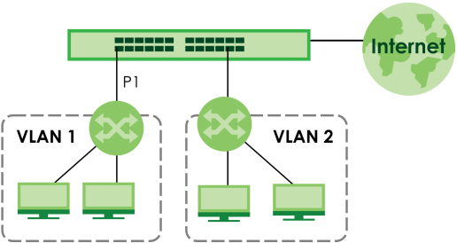
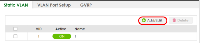
1 Go to the SWITCHING > VLAN > Static VLAN screen. Click Add/Edit.
2 The following screen appears. Click the switch to set this VLAN to Active, enter a descriptive name in the Name field and enter “2” in the VLAN Group ID field for the VLAN2 network.
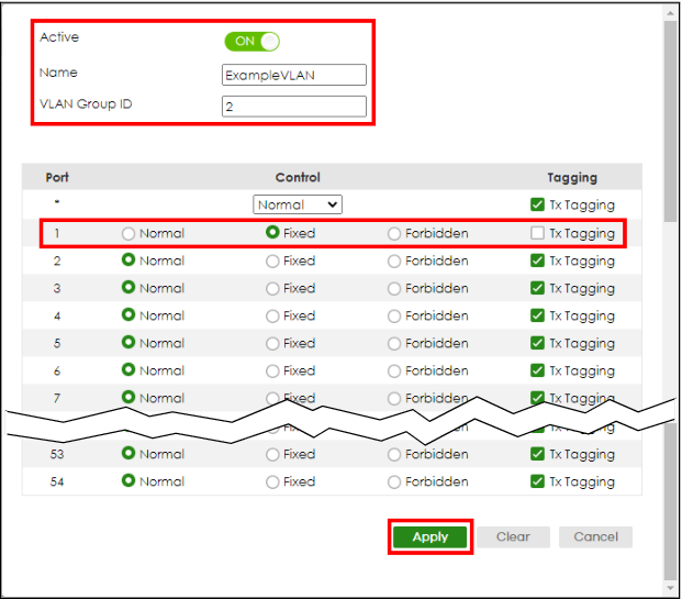
 The VLAN Group ID field in this screen and the VID field in the SYSTEM > IP Setup > IP Status screen refer to the same VLAN ID.
3 Since the VLAN2 network is connected to port 1 on the Switch, select Fixed to configure port 1 to be a permanent member of the VLAN only.
4 To ensure that VLAN-unaware devices (such as computers and hubs) can receive frames properly, clear the Tx Tagging checkbox to set the Switch to remove VLAN tags before sending.
5 Click Apply to save the settings to the run-time memory. Settings in the run-time memory are lost when the Switch’s power is turned off.
Set Port VID
Use PVID to add a tag to incoming untagged frames received on that port so that the frames are forwarded to the VLAN group that the tag defines.
In the example network, configure 2 as the port VID (PVID) on port 1 (P1) so that any untagged frames received on that port get sent to VLAN 1.
Getting Started: Port VID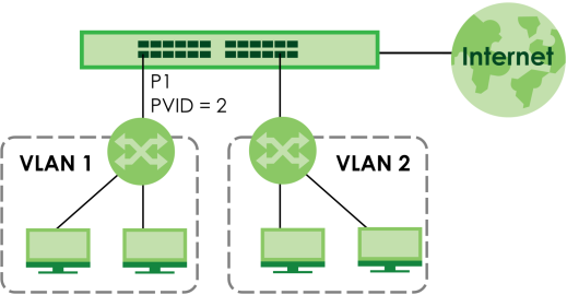
1 Go to the SWITCHING > VLAN > VLAN Setup > VLAN Port Setup screen.
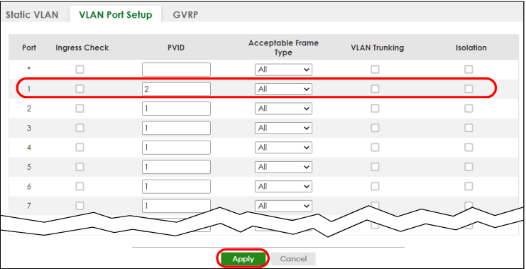
2 Enter 2 in the PVID field for port 1 and click Apply to save your changes back to the run-time memory. Settings in the run-time memory are lost when the Switch’s power is turned off.
Configure Switch Management IP Address
If the Switch fails to obtain an IP address from a DHCP server, the Switch will use 192.168.1.1 as the management IP address. You can configure another IP address in a different subnet for management purposes. The following figure shows an example.
Getting Started: Management IP Address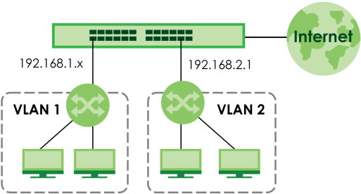
1 Connect your computer to any Ethernet port on the Switch. Make sure your computer is in the same subnet as the Switch.
2 Open your web browser and enter “setup.zyxel” or “192.168.1.1” (the default IP address) in the address bar to access the Web Configurator. See System Login for more information.
You can always use the domain name “setup.zyxel” to access the Web Configurator whether the Switch is using a DHCP-assigned IP or static IP address. This requires your PC to be directly connected to the Switch.3 Go to the SYSTEM > IP Setup > IP Setup screen. Click Add/Edit.
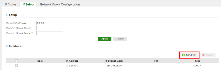
The following screen appears.
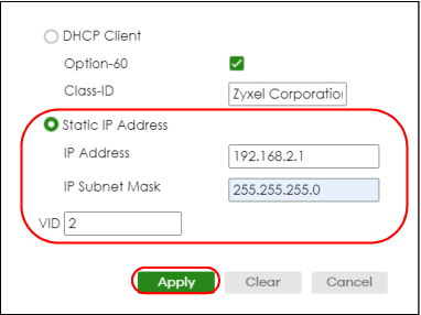
4 For the VLAN2 network, enter 192.168.2.1 as the IP address and 255.255.255.0 as the subnet mask.
5 In the VID field, enter the ID of the VLAN group to which you want this management IP address to belong. In this example, enter VLAN ID 2. This is the same as the VLAN ID you configure in the Static VLAN screen.
6 Click Apply to save your changes back to the run-time memory. Settings in the run-time memory are lost when the Switch’s power is turned off.
How to Use DHCPv4 Snooping on the Switch
You only want DHCP server A connected to port 5 to assign IP addresses to all devices in VLAN network. Create a VLAN containing ports 4, 5 and 6. Connect a computer to the Switch for management.
Tutorial: DHCP Snooping Tutorial Overview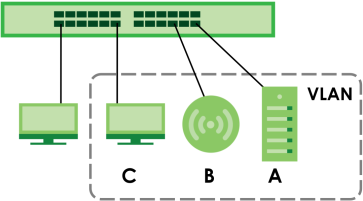
The settings in this tutorial are as the following.
Host | Port connected | VLAN | PVID | DHCP Snooping port trusted |
|---|---|---|---|---|
DHCP Server (A) | 4 | 1 and 100 | 100 | Yes |
DHCP Client (B) | 5 | 1 and 100 | 100 | No |
DHCP Client (C) | 6 | 1 and 100 | 100 | No |
1 Connect your computer to the out-of-band management port (so you can access the Switch without being affected by any IP change caused by configurations). Access the Switch through http://192.168.0.1. Access the Switch through http://192.168.1.1 by default. Log into the Switch by entering the user name (default: admin) and password (default: shown on the back label on the Switch).
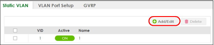
2 Go to SWITCHING > VLAN > VLAN Setup > Static VLAN. Click Add/Edit.
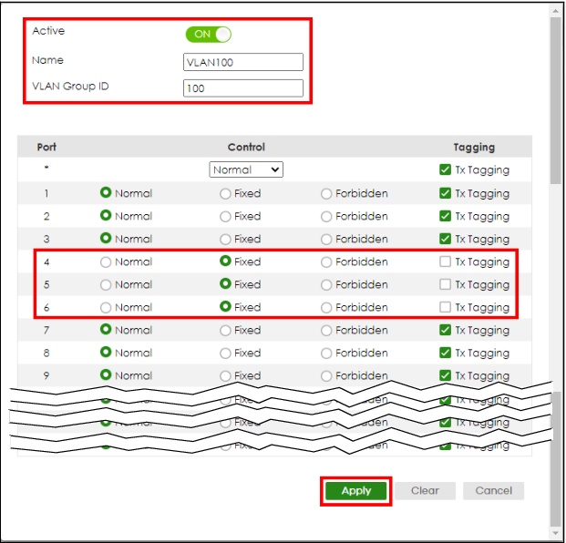
3 The following screen appears. Enable the switch button to set this VLAN to ACTIVE. Create a VLAN with ID of 100. Add ports 4, 5 and 6 in the VLAN by selecting Fixed in the Control field as shown.
De-select Tx Tagging because you do not want outgoing traffic to contain this VLAN tag.
Click Apply.
4 Go to SWITCHING > VLAN > VLAN Setup > VLAN Port Setup, and set the PVID of the ports 4, 5 and 6 to 100. This tags untagged incoming frames on ports 4, 5 and 6 with the tag 100. Click Apply.
Tutorial: Tag Untagged Frames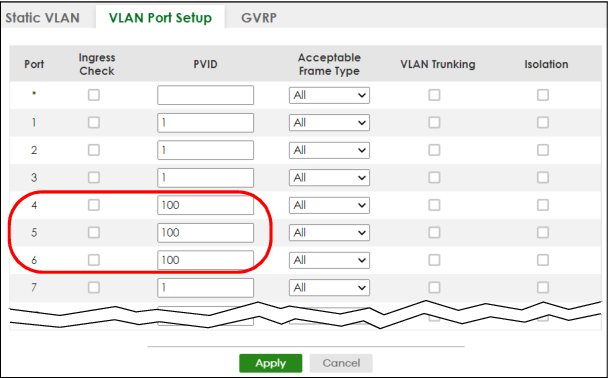
5 Go to SECURITY > DHCP Snooping > DHCP Snp. Setup, activate and specify VLAN 100 as the DHCP VLAN as shown. Click Apply.
IP requests from VLANs you enable on the SECURITY > DHCP Snooping > DHCP Snp. VLAN Setup screen will be broadcast to the DHCP VLAN you set on this screen, which is VLAN100 in this example.
IP requests from VLANs you enable on the SECURITY > DHCP Snooping > DHCP Snp. VLAN Setup screen will be broadcast to the DHCP VLAN you set on this screen, which is VLAN100 in this example.
Tutorial: Specify DHCP VLAN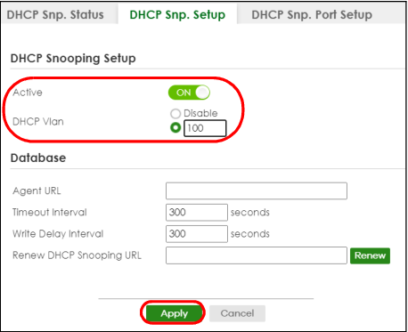
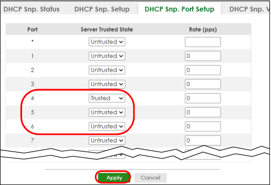
6 Go to SECURITY > DHCP Snooping > DHCP Snp. Port Setup. Select Trusted in the Server Trusted state field for port 4 because the DHCP server is connected to port 4. Keep ports 5 and 6 Untrusted because they are connected to DHCP clients. Click Apply.
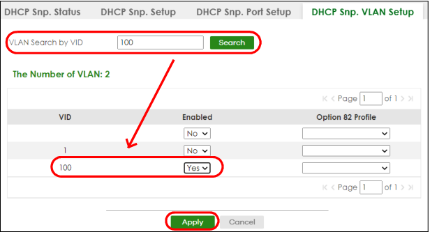
7 Go to SECURITY > DHCP Snooping > DHCP Snp. VLAN Setup, show VLAN 100 by entering 100 in the VLAN Search by VID field and click Search.
Select Yes in the Enabled field of the VLAN 100 entry shown in the search result. Click Apply.
Select Yes in the Enabled field of the VLAN 100 entry shown in the search result. Click Apply.
This enables DHCP snooping on VLAN100 (and other VLANs you enabled on this screen).
If you want the Switch to add more information in the DHCP request packets, such as source VLAN ID or system name, you can select an Option82 Profile in the entry. The Switch will add DHCP option 82 information to DHCP requests that the Switch relays to a DHCP server for the specified VLAN.
8 Connect your DHCP server to port 4 and a DHCP client (an AP, for example) to either port 5 or 6. The AP should be able to get an IP address from the DHCP server. If you put the DHCP server on port 5 or 6, the computer will NOT be able to get an IP address.
9 Click Save at the top right of the Web Configurator to save the configuration permanently.

10 To check if DHCP snooping works, go to SECURITY > IPv4 Source Guard > IP Source Guard, you should see an IP assignment with the type DHCP-Snooping as shown.
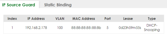
You can also use telnet. Use the command “show dhcp snooping binding” to see the DHCP snooping binding table as shown next.
sysname# show dhcp snooping binding MacAddress IpAddress Lease Type VLAN Port ----------------- --------------- ------------ ------------- ---- ----- 88:88:88:88:88:8b 192.168.2.178 0d23h59m20s dhcp-snooping 100 5 Total number of bindings: 1 |
How to Use DHCPv4 Relay on the Switch
This tutorial describes how to configure your Switch to forward DHCP client requests to a specific DHCP server. The DHCP server can then assign a specific IP address based on the information in the DHCP requests.
DHCP Relay Tutorial Introduction
In this example, you have configured your DHCP server (192.168.2.3) and want to have it assign a specific IP address (say 172.16.1.18) to DHCP client A based on the system name, VLAN ID and port number in the DHCP request. Client A connects to the Switch’s port 2 (P2) in VLAN 102.
Getting Started: DHCP Relay Scenario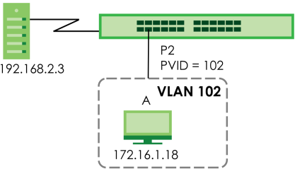
Create a VLAN
Follow the steps below to configure port 2 as a member of VLAN 102.
1 Access the Web Configurator through the Switch’s management port.
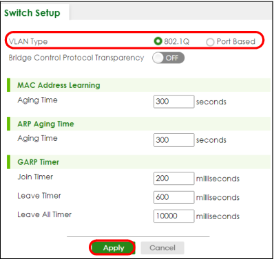
2 Go to SYSTEM > Switch Setup > Switch Setup and set the VLAN Type to 802.1Q. Click Apply to save the settings to the run-time memory.
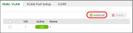
3 Go to SWITCHING > VLAN > VLAN Setup > Static VLAN. Click Add/Edit.
4 The following screen appears. Enable the switch button to set this VLAN to Active. Enter a descriptive name (VLAN 102 for example) in the Name field and enter “102” in the VLAN Group ID field.
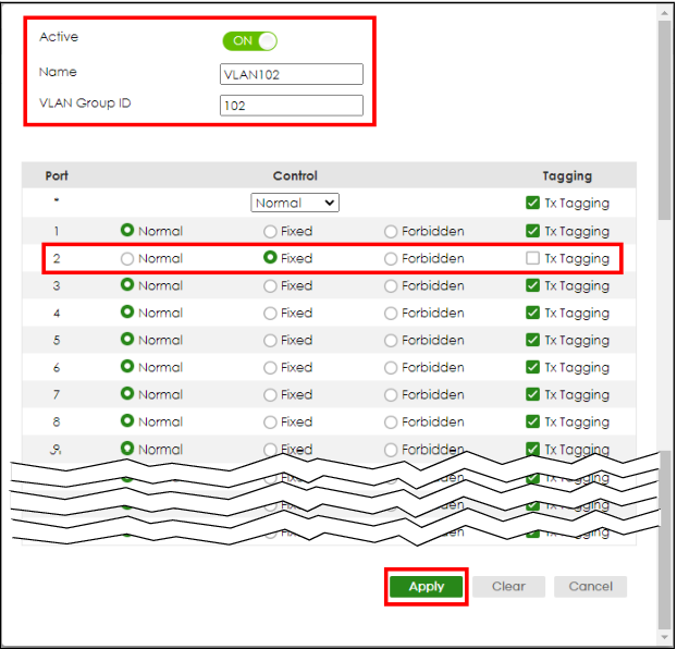
5 Set port 2 to be a permanent member of this VLAN by selecting Fixed in the Control field.
6 Clear the Tx Tagging checkbox to set the Switch to remove VLAN tags before sending.
7 Click Apply to save the settings to the run-time memory. Settings in the run-time memory are lost when the Switch’s power is turned off.
8 Go to VLAN > VLAN Setup > VLAN Port Setup. Enter “102” in the PVID field for port 2 to add a tag to incoming untagged frames received on that port so that the frames are forwarded to the VLAN group that the tag defines.
9 Click Apply to save your changes back to the run-time memory.
10 Click the Save link in the upper right of the Web Configurator to save your configuration permanently.
Configure DHCPv4 Relay
Follow the steps below to enable DHCP relay on the Switch and allow the Switch to add relay agent information (such as the VLAN ID) to DHCP requests.
1 Click NETWORKING > DHCP > DHCPv4 Relay > DHCP Smart Relay. Enable the Active switch button.
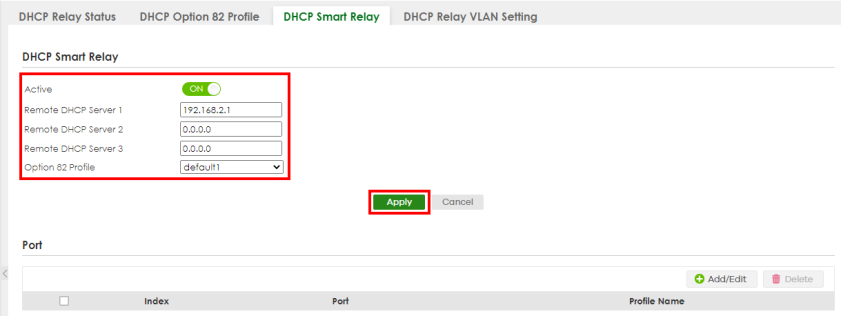
2 Enter the DHCP server’s IP address (192.168.2.3 in this example) in the Remote DHCP Server 1 field.
3 Select default1 or default2 in the Option 82 Profile field.
4 Click Apply to save your changes back to the run-time memory.
5 Click the Save link in the upper right of the Web Configurator to save your configuration permanently.
6 The DHCP server can then assign a specific IP address based on the DHCP request.
Troubleshooting
Check client A’s IP address. If it did not receive the IP address 172.16.1.18, make sure:
1 Client A is connected to the Switch’s port 2 in VLAN 102.
2 You configured the correct VLAN ID, port number and system name for DHCP relay on both the DHCP server and the Switch.
3 You clicked the Save link on the Switch to have your settings take effect.
How to Use Auto Configuration through a DHCP Server on the Switch
Follow the steps below to set up configurations on a DHCP server, TFTP server, and the Switch, so you can load an auto configuration file automatically from a TFTP server when you reboot the Switch.
Note that you can set up a DHCP server and TFTP server either on the same device or different devices. Also, make sure the Switch can communicate with the TFTP server.
Steps order could vary according to different programs you use.You need to set up configurations on a DHCP server and TFTP server first to use auto configuration.Setting up a DHCP Server
1 Set up a dynamic IP addresses pool so the DHCP server will assign an IP address to the Switch in that range.
2 Set up a TFTP server IP address, so the Switch will know where to load the auto configuration file.
3 Set up the filename of the auto configuration file, so the Switch will know which file to load when you reboot the Switch.
• Enter the filename of an auto configuration file. The Switch will load this auto configuration file when rebooting with DHCP option 60 disabled.
• If you want to load the auto configuration file with DHCP option 60 enabled and a Vendor Class Identifier assigned when you reboot the Switch, follow the instruction below. Otherwise, skip this step.
Enter the filename of an auto configuration file. Set up a Vendor Class Identifier. To have the Switch load this auto configuration file, two conditions listed above must be met. Please refer to the following steps to see how to set up a Vendor Class Identifier on the Switch.
Enter the filename of an auto configuration file. Set up a Vendor Class Identifier. To have the Switch load this auto configuration file, two conditions listed above must be met. Please refer to the following steps to see how to set up a Vendor Class Identifier on the Switch.
Setting up a TFTP Server
1 Select a directory on the TFTP server.
2 Put the configuration files in that directory.
Setting Up the Switch
1 Open the Web Configurator. Go to the MAINTENANCE > Configuration > Auto Configuration > Auto Configuration screen.
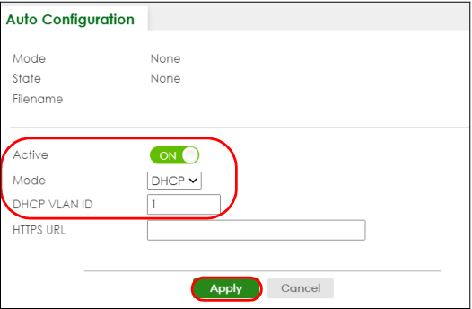
2 Enable the switch button in the Active field to enable auto configuration. Select DHCP in the Mode field, and enter the VLAN ID where the DHCP server belongs to in the DHCP VLAN ID field. Click Apply to save your changes.
3 Go to the SYSTEM > IP Setup > IP Setup screen. Click the Add/Edit button in the IP Interface table to open the configuration screen.
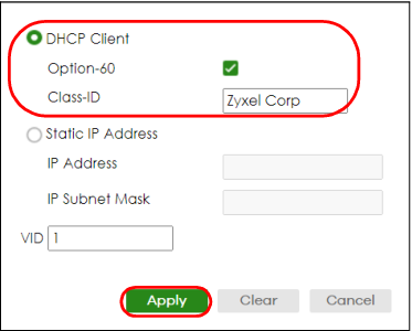
4 Select DHCP Client.
5 If you want to load the auto configuration file with DHCP option 60 enabled and a Vendor Class Identifier assigned when you reboot the Switch, follow the instruction below. Otherwise, skip this step. In the SYSTEM > IP Setup > IP Setup > Add/Edit screen, select the checkbox in the Option-60 field. Enter a Vendor Class Identifier in the Class-ID field, and specify the VLAN interface in the VID field. In this example, we use “Zyxel Corp” and VID 1. Click Apply.
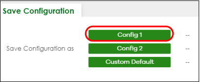
6 You need to save the current configuration in a configuration file, so the Switch will load the auto configuration file from the TFTP server automatically when rebooting. Go to the MAINTENANCE > Configuration > Save Configuration > Save Configuration screen. Click the Config 1, Config 2, or Custom Default button.
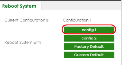
7 Click the same button in the MAINTENANCE > Reboot System > Reboot System screen to reboot the Switch, and load the auto configuration setting as configured before. For example, if you save the auto configuration setting to Config 1, you need to click the Config 1 button in the Reboot System screen.
8 Go to the MONITOR > System Log > System Log screen to see if auto configuration was performed successfully.
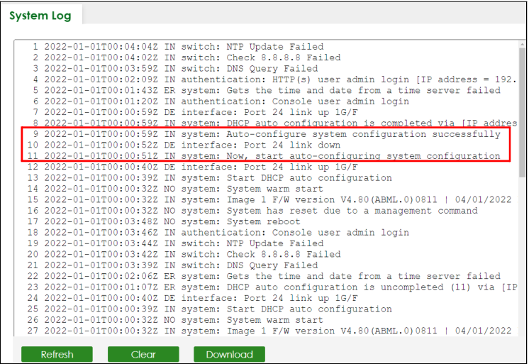
9 Check the screens to see if it is the configuration file you want to load. If it is not, go through the steps above to check your configurations. If it is, click Save at the top right corner of the Web Configurator to save the configuration permanently.
How to Back Up the Configuration
This section shows you how to back up the configuration. You should regularly back up your configuration especially before you make major configuration changes.
1 Log into the Web Configurator. Go to MAINTENANCE > Configuration > Backup Configuration > Backup Configuration.
2 Select the configuration you want to back up from the drop-down list. In this tutorial, you want to back up the currently running configuration, select Running Config.
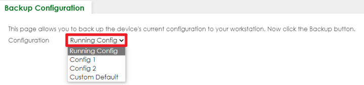
3 Click Backup.

4 Save the downloaded file to your computer.
How to Restore the Configuration
This section shows you how to restore a previously saved configuration file from your computer to the Switch.
1 Log into the Web Configurator. Go to MAINTENANCE > Configuration > Restore Configuration > Restore Configuration.
2 Click Choose File and select the previously saved configuration file.

3 Click Restore.

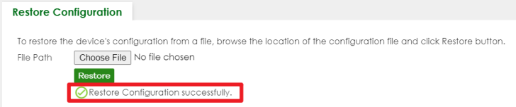
4 The Switch is now running with the uploaded configuration.
How to Upgrade the Firmware
This section shows you how to upgrade the Switch’s firmware through NCC, the Web Configurator. You should always use the most recent firmware to get the latest features, improvements, and bug fixes.
Firmware Upgrade Through NCC
Follow the steps below to upgrade the firmware to the Switch.
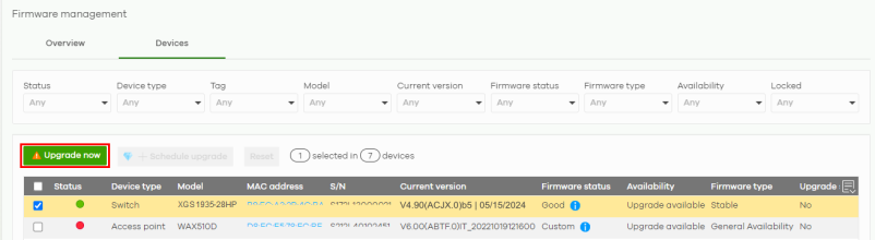
1 Log into the NCC. Go to Site-wide > Configure > Firmware management > Devices. Find the Switch in the device list. The Availability of the Switch is Upgrade available when a newer firmware is available.
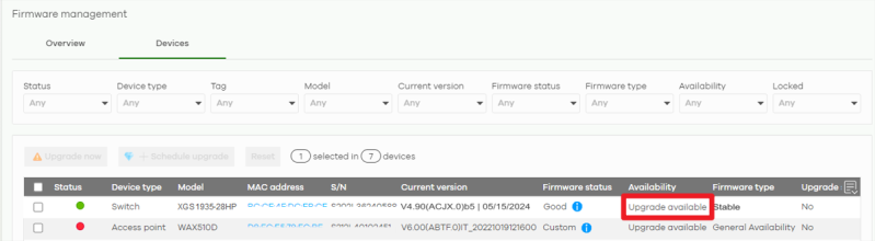
2 Select the checkbox of the Switch, then click Upgrade now.
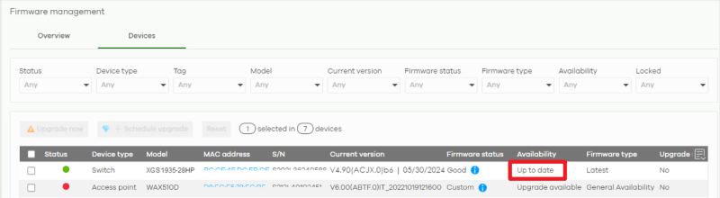
3 Check that the Availability of the Switch is Up to date.
 ㄅ
ㄅFirmware Upgrade Through the Web Configurator
Follow the steps below to download the firmware from the Zyxel website first, then upgrade the Switch’s firmware through the Web Configurator.
Download the Firmware
Follow the steps below to download the firmware.
2 Search for the model number of the Switch.
3 Download the firmware to your computer and then unzip it.
Upgrade the Firmware
The Switch supports dual firmware images, Firmware 1 and Firmware 2. You can apply one of these images as an active image, and the other one as a backup image. Follow the steps below to upload and apply the firmware to the Switch.
Only the active image is loaded when the Switch starts up.1 Log into the Web Configurator. Go to MAINTENANCE > Firmware Upgrade > Firmware Upgrade.
2 Select the firmware you want to upgrade from the drop-down list. In this tutorial, you want to upload the downloaded firmware to Firmware 1 on the Switch. Select 1.

3 Click Choose File and select the downloaded, unzipped firmware file.

4 Click Upgrade to upload the new firmware.

5 The upgraded firmware will display in Firmware Upgrade. Check that the version is correct for Firmware 1.
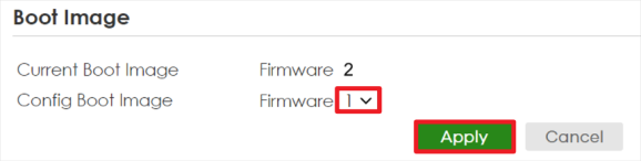
6 The Switch is currently using Firmware 2. To allow the Switch to use Firmware 1, select 1 from Config Boot Image, then click Apply.
7 Unplug the power cable and then plug it back into the Switch. Close the current window of the Web Configurator, then log into the Web Configurator with a new window.
8 Go to MAINTENANCE > Firmware Upgrade > Firmware Upgrade. Check that the Running firmware is the same as Firmware 1 version.