Devices
Use the Devices menus to check Nebula Device information, client information, event log messages and summary report for Nebula Devices in the selected site.
Access Points
This screen allows you to view the detailed information about a Nebula AP in the selected site. Click Site-wide > Devices > Access point to access this screen.
Site-wide > Devices > Access point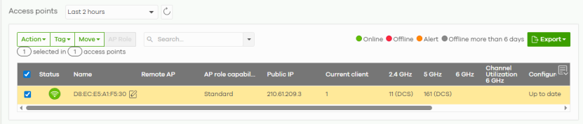
The following table describes the labels in this screen.
Label | Description |
|---|---|
Access points | Select to view device information and connection status in the past 2 hours, day, week, month. |
 | Click this button to reload the data-related frames on this page. |
Action | Perform an action on the selected Nebula APs. |
Reboot | Select this to restart the Nebula AP. |
Upgrade | Select this to upgrade the firmware on the Nebula AP. |
Change PSK | Select this to generate a random Pre-Shared Key, or use a custom Pre-Shared Key. This allows a user to access the WiFi network through the Nebula AP. 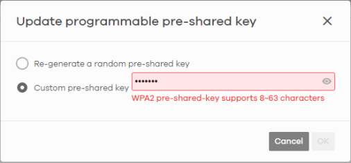  Programmable SSID must be enabled in Site-wide > Configure > WiFi SSID. |
Change PTMP bandwidth control | Click this to add the Nebula AP(s) to or remove them from the selected PTMP bandwidth control rule. 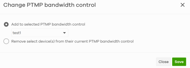 This option is available only when all selected Nebula APs support this feature. Otherwise, this button is grayed out. |
Tag | Select one or multiple Nebula APs and click this button to create a new tag for the Nebula APs or delete an existing tag. |
Move | Select one or multiple Nebula APs and click this button to move the Nebula APs to another site or remove the Nebula APs from the current site. |
AP Role | Select one or multiple Nebula APs and click this button to enable or disable the Remote AP feature. Remote Nebula Device enables the site’s Security Appliance to connect to the Nebula AP through a secure VPN tunnel. This allows you to set up VPN-enabled WiFi Nebula APs in remote locations, such as in a branch office or at home. Clients connected to these Nebula APs can securely access your network through the VPN tunnel. Enabling Remote Nebula Device automatically enables Ethernet and wireless storm control on the Nebula AP. |
Search | Specify your desired filter criteria to filter the list of Nebula APs. |
access points | This shows the number of Nebula APs connected to the site network. |
Export | Click this button to save the access point list as a CSV or XML file to your computer. |
* | Click this to select all the rows in this table. |
Device | |
Current version | This shows the firmware version currently installed on the Nebula AP. |
Description | This shows the user-specified description for the Nebula AP. |
MAC address | This shows the MAC address of the Nebula AP. |
Model | This shows the model number of the Nebula AP. |
MSP product ID | Enter the unique product ID designated by the MSP to identify your Nebula AP. You can use alphanumeric and ()+/:=?!*#@$_%- characters, and it can be up to 64 characters. |
Name | This shows the descriptive name of the Nebula AP. Click the Edit icon to change the Nebula AP name. |
Product information | This shows the specification of the Nebula AP. |
Serial number | This shows the serial number of the Nebula AP. |
Tag | This shows the user-specified tag for the Nebula AP. |
Status | |
Configuration status | This shows whether the configuration on the Nebula AP is up-to-date. When it shows Not up to date, require upgrade to latest firmware., click the iNote and click upgrade now. On the confirmation screen click Ok to install the latest firmware for the Nebula AP. |
Connectivity | This shows the access point connection status. The red time slot indicates the connection to the NCC is down, and the green time slot indicates the connection is up. Move the cursor over a time slot to see the actual date and time when an Nebula AP is connected or disconnected. |
Power mode | This shows the Nebula AP’s power status. Full – the Nebula AP receives power using a power adapter and/or through a PoE switch/injector using IEEE 802.3at PoE plus. The PoE device that supports IEEE 802.3at PoE Plus can supply power of up to 30W per Ethernet port. Limited – the Nebula AP receives power through a PoE switch/injector using IEEE 802.3af PoE even when it is also connected to a power source using a power adapter. The PoE device that supports IEEE 802.3af PoE can supply power of up to 15.4W per Ethernet port. When the Nebula AP’s power mode is Limited, the Nebula AP throughput decreases and has just one transmitting radio chain. It always shows Full if the Nebula AP does not support power detection. |
Status | This shows the status of the Nebula AP. • Green: The Nebula AP is online and has no alerts. • Amber: The Nebula AP has alerts. Hover the mouse over the icon to find the problem. • Red: The Nebula AP is offline. • Gray: The Nebula AP has been offline for 7 days or more. •  : The Nebula AP is acting as a repeater. For example, an alert is created and the status color is amber when the Nebula AP is transmitting data at 100 Mbps in half duplex mode or when the Nebula AP is in a Limited Power mode. Click the Nebula AP on this page to go to the Nebula AP’s details screen for more information. |
Usage | |
% Usage | This shows the percentage of the Nebula AP’s data usage relative to other Nebula Devices. |
Client | This shows how many clients are connected to the Nebula AP within the specified time period. |
Current client | This shows how many clients are currently connecting to the Nebula AP. |
Usage | This shows the amount of data consumed by the Nebula AP’s clients. |
Wireless | |
2.4GHz | This shows the number of WiFi clients in the 2.4 GHz band. |
5GHz | This shows the number of WiFi clients in the 5 GHz band. |
6GHz | This shows the number of WiFi clients in the 6 GHz band. |
Channel Utilization 2.4GHz | This shows the percentage of the 2.4 GHz channel ID usage. |
Channel Utilization 5GHz | This shows the percentage of the 5 GHz channel ID usage. |
Channel Utilization 6GHz | This shows the percentage of the 6 GHz channel ID usage. |
Uplink | |
Ethernet 1 | This shows the speed and duplex mode of the Ethernet connection on the Nebula AP’s up-link port. It shows Down if the Nebula AP is connected to a mesh controller wirelessly. |
IP type | This shows whether the IP address was assigned automatically (DHCP), or manually (Static IP). |
LAN IP | This shows the local (LAN) IP address of the Nebula AP. |
Neighbor Info | This shows the LLDP information received on the up-link port. |
Public IP | This shows the global (WAN) IP address of the Nebula AP. |
Uplink | This shows whether the Nebula AP is connected to the gateway through a wired Ethernet connection or WiFi connection. |
Mesh | |
Hop | This shows the hop count of the Nebula AP. For example, “1” means the Nebula AP is connected to a mesh controller directly. “2” means there is another mesh extender between this Nebula AP and the mesh controller. |
Uplink AP | This shows the role and descriptive name of the Nebula AP to which this Nebula AP is connected wirelessly. When Smart Mesh is enabled and the mesh extender losses connection to the mesh controller, click Reconnect to re-establish connection. Make sure to enable Manual uplink in Site-wide > Devices > Access points: Details > Status > Smart mesh > Edit. You also need to specify the mesh controller in select an AP. See Site-wide > Devices > Access point: Details for more information. |
Uplink signal | Before the slash, this shows the signal strength the uplink Nebula AP (a mesh controller or a mesh extender) receives from this Nebula AP (in repeater mode). After the slash, this shows the signal strength this Nebula AP (in repeater mode) receives from the uplink access point. |
Uplink Tx/Rx rate | This is the maximum transmission/reception rate of the mesh controller or mesh extender to which the Nebula AP is connected. |
Wireless bridge | This shows whether wireless bridge is enabled on the Nebula AP. For more information about wireless bridge, see Wireless Bridge. |
RAP | |
AP Role Capability | This displays whether the Nebula AP can act as a remote Nebula AP (Remote AP) or not (Standard AP). |
Remote AP | This shows whether the Remote Nebula AP function is Enabled or Disabled. |
Remote AP VPN | This shows which VPN the Remote Nebula AP tunnel is configured to use. If Remote Nebula AP is disabled, this field shows Disconnected. |
Firmware | |
Firmware availability | This shows whether the firmware on the Nebula AP is Up to date, there is firmware update available for the Nebula AP (Upgrade available), or a specific version of firmware has been installed by Zyxel customer support (Locked). |
Firmware status | This shows whether the firmware installed on the Nebula AP is up-to-date. |
Firmware type | This shows Stable when the installed firmware may not have the latest features but has passed Zyxel internal and external testing. This shows Latest when the installed firmware is the most recent release with the latest features, improvements, and bug fixes. This shows General Availability when the installed firmware is a release before Latest, but is newer than stable and is still undergoing Zyxel external testing. This shows Dedicated when the installed firmware is locked and Zyxel support is monitoring. Contact Zyxel customer support if you want to unlock the firmware in order to upgrade to a later one. This shows Beta when the installed firmware is a release version for testing the latest features and is still undergoing Zyxel internal and external testing. This shows N/A when the Nebula AP is offline and its firmware status is not available. |
PTMP | |
PTMP bandwidth control | This shows the PTMP Bandwidth Control rule selected for this Nebula AP. This field is blank when no rule is selected or the Nebula AP does not support this feature. |
 | Click this icon to display a greater or lesser number of configuration fields. For faster loading of data, select only the configuration fields listed that do NOT take a long time to fetch data. |
Access Point Details
Click a Nebula AP entry in the Site-wide > Devices > Access point screen to display individual Nebula AP statistics.
Site-wide > Devices > Access point: Details Part 1 (WBE660S)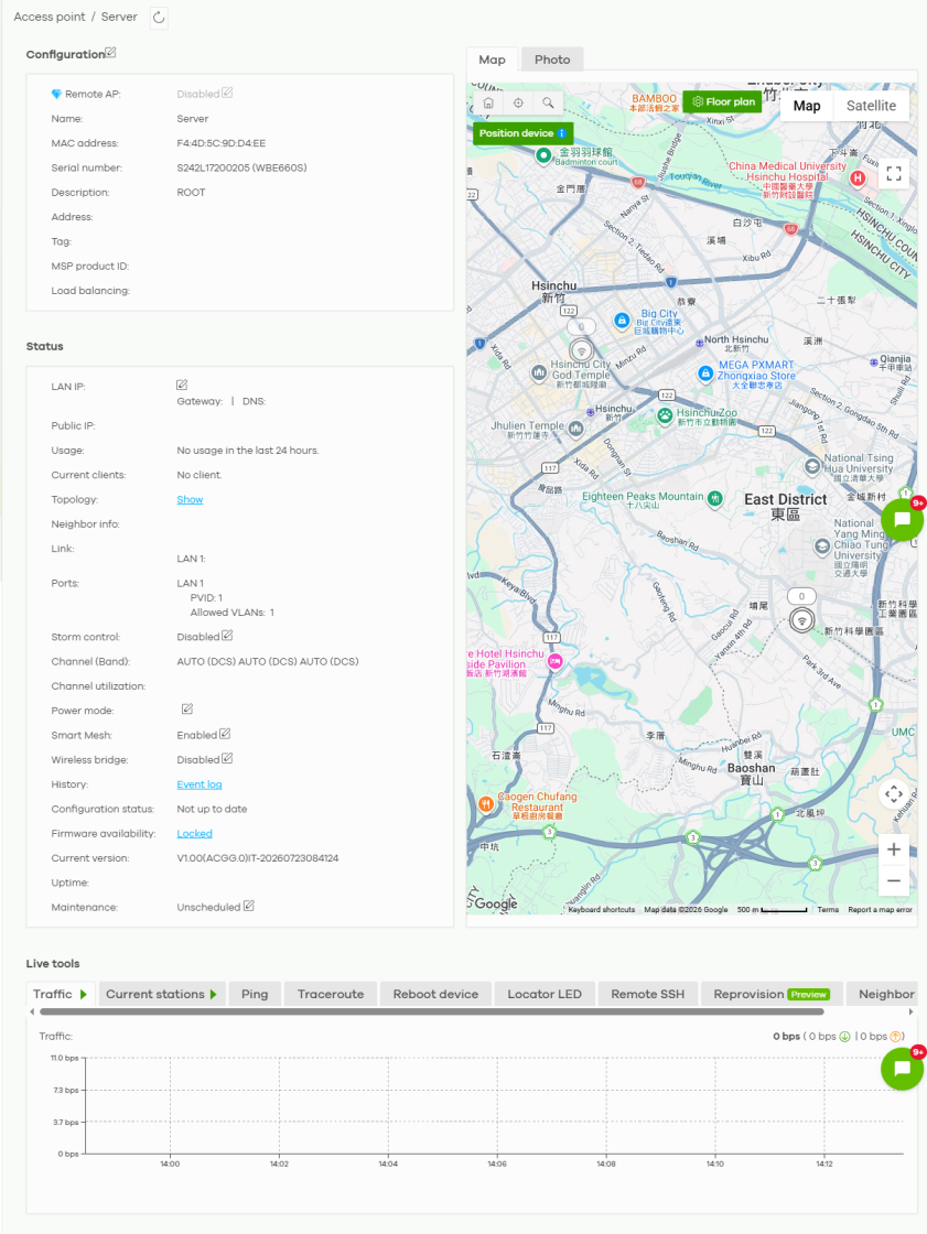
Site-wide > Devices > Access point: Details Part 2 (WBE660S)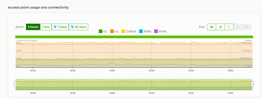
Site-wide > Devices > Access point: Details Part 1 (Root Plus)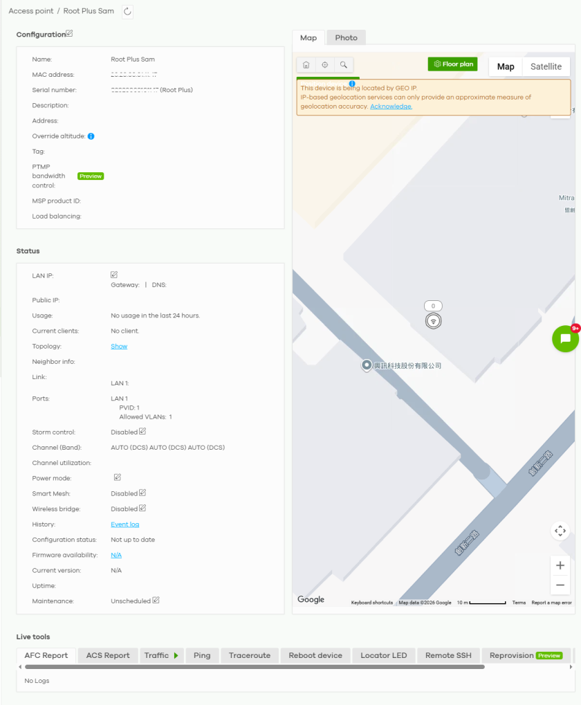
Site-wide > Devices > Access point: Details Part 2 (Root Plus)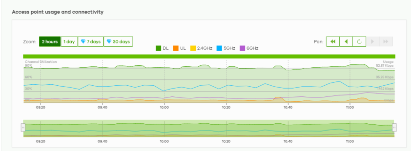
The following table describes the labels in this screen.
Label | Description |
|---|---|
 | Click this button to reload the data-related frames on this page. |
Configuration Click the edit configuration icon to change the Nebula AP name, description, tags, load balancing, and address. You can move the Nebula AP to another site or remove. You can also enter a valid Address and click Move map marker to move the Nebula AP to another location. By default, the Nebula AP’s hostname is the MAC address. Enter a Name to identify the Nebula AP. You can use up to 64 alphanumeric characters including period (.) and hyphen (-). Spaces are not allowed. The period (.) and hyphen (-) cannot be the first character, last character, or appear consecutively on the Name. For example, -wax650, wax650-, wax650..wax650, wax650.-wax650.The Name you configure here will be synchronized with the Nebula AP’s System Name setting when: • The Nebula AP must have firmware version 6.60 or later • The Name follows the [Hostname] or [Hostname.Domain name] format • The domain name follows the standard DNS structure [A.B.C.D]. Then click Save to save your changes. | |
Remote AP | Click this to enable or disable the Remote AP feature. Remote AP enables the site’s Security Appliance to connect to the Nebula AP through a secure VPN tunnel. This allows you to set up VPN-enabled WiFi Nebula APs in remote locations, such as in a branch office or at home. Clients connected to these Nebula APs can securely access your network through the VPN tunnel. With the Remote AP feature (in the Secure WiFi license) the connection is from the Nebula AP to a managed access point using NVGRE (Network Virtualization using Generic Routing Encapsulation) over IPSec tunnel. This encapsulates and encrypts traffic from the remote access point to the Nebula AP. The clients connected to the remote access point do not need IPSec client software installed. Enabling Remote AP automatically enables Ethernet and wireless storm control on the Nebula AP.At the time of writing, both the SSID Secure Tunnel Setting for Remote AP Setting and the Ethernet secure tunnel setting features are available for WAC500H only. Only the SSID Secure Tunnel Setting feature is available for the other supported Nebula APs. See AP & Port Settings for more information on Ethernet secure tunnel setting. 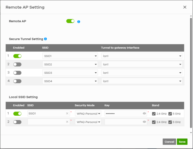 Configure and enable up to two SSID(s) in Local SSID Setting. WiFi clients connected to these SSIDs are forwarded to the local network of the remote site. The Local SSID Setting are different from the SSIDs you configured in Site-wide > Configure > Access points > SSID advanced settings. See SSID Advanced Settings for the description of the fields. Select from the available LAN interface in Tunnel to gateway interface to enable it, and click Save. |
Name | This shows the descriptive name of the Nebula AP. |
MAC address | This shows the MAC address of the Nebula AP. |
Serial number | This shows the serial number of the Nebula AP. |
Change site | Select the new site from the drop-down menu or click Remove to remove the Nebula AP from the site. |
Description | This shows the user-specified description for the Nebula AP. |
Address | This shows the user-specified address for the Nebula AP. |
Override altitude | To comply with the US FCC mandated AFC (Automated Frequency Coordination) system for WiFi 6E outdoor devices, accurate altitude information is required for Root Plus and Leaf Plus. Overriding the GPS-derived altitude setting for outdoor Access Points (APs) is done to ensure correct radio frequency (RF) propagation calculations, particularly for long-distance, outdoor, or bridge deployments where automatic GPS location might be inaccurate. Enter the ‘Above Mean Sea Level’ (AMSL) in meters (–9999.99 to 9999.99) to override the GPS-derived altitude value. To get an accurate AMSL value: 1. Determine the ground elevation: Find the precise AMSL elevation of the ground at the installation site using high-resolution survey data or tools like the USGS Elevation Point Query Service or Google Earth. 2. Add the mounting height: Measure the distance from the ground level to the Nebula AP's actual mounting position (antenna height). (Ground Elevation) + (Mounting Height) = Total AMSL. |
Tag | This shows the user-specified tag for the Nebula AP. |
PTMP bandwidth control | Select a PTMP bandwidth control rule from the drop-down list to apply to this Nebula AP. A Nebula AP can only have one PTMP bandwidth control rule. Configure the rules in Site-wide > Configure > Access points > Traffic shaping > PTMP bandwidth control. See PTMP Bandwidth Control for more information. 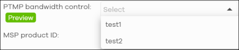 This field is only available on Nebula APs that support PTMP bandwidth control. To see the supported models, go to Site-wide > Configure > Access points > Traffic shaping > PTMP bandwidth control, click Model list. |
MSP product ID | Enter the unique product ID designated by the MSP to identify your Nebula AP. You can use alphanumeric and ()+/:=?!*#@$_%- characters, and it can be up to 64 characters. |
Load balancing | This shows the load balancing group name that the Nebula AP belongs (up to two groups per access point). Nebula APs in the same group should be within the proximity. This allows them to share the load. |
Status | |
LAN IP | This shows the local (LAN) IP address of the Nebula AP. It also shows the IP addresses of the gateway and DNS server. Click the edit icon to open a screen where you can change the IP addresses, VLAN ID number and tagging setting. 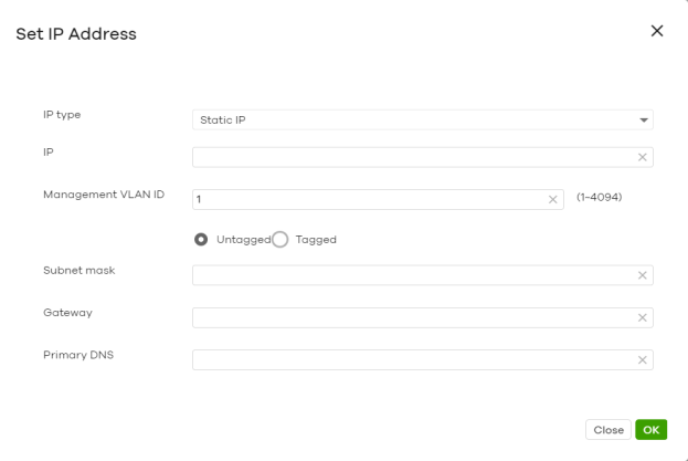 To prevent an IP address conflict, NCC will prevent input of an IP address already used by another Nebula Device in the same site. |
Public IP | This shows the global (WAN) IP address of the Nebula AP. |
Usage | This shows the amount of data consumed by the clients. |
Current clients | This shows the number of clients which are currently connecting to the Nebula AP and its details. |
Topology | |
Neighbor info | This shows the LLDP information received on the up-link port. |
Link | This shows the speed and duplex mode of the Ethernet connection on the Nebula AP’s ports. It shows Uplink: Wireless if the access point is an mesh extender and connected to a mesh controller wirelessly. A warning icon displays when the Nebula AP is running at 100 Mbps or a lower speed. |
Ports | This is available only for the Nebula AP that has one or more than one Ethernet LAN port (except the uplink port). This shows the PVID of the LAN port and the ID number of VLANs to which the LAN port belongs. See AP & Port Settings for how to change the port’s VLAN settings. |
Storm control | Storm control limits the number of broadcast, multicast and destination lookup failure (DLF) packets received per second on the Nebula AP’s Ethernet ports. When the maximum number of allowable broadcast, multicast and/or DLF packets is reached per second, the subsequent packets are discarded. Enabling this feature reduces broadcast, multicast and/or DLF packets in your network. |
Installation environment | This shows whether the Nebula AP is installed Outdoors or Indoors. For regulatory compliance, the 6 GHz WiFi band will automatically be disabled when you select Outdoor. Conversely, the 6 GHz WiFi band will automatically be enabled when you select Indoor. |
Channel (Band) | This shows the channel ID and WiFi frequency band currently being used by the Nebula AP. |
Channel utilization | This shows the percentage of the channel ID usage. |
Power mode | This shows Full when the Nebula AP receives power directly through a power outlet. This shows Full (Power by DC) when the Nebula AP receives power using a power adapter. This shows Full (Power by PoE) when the Nebula AP receives power through a PoE switch/injector using IEEE 802.3at PoE plus. The PoE device that supports IEEE 802.3at PoE Plus can supply power of up to 30W per Ethernet port. This shows Limited (Require 802.3bt power) when the Nebula AP receives power through a PoE switch/injector using IEEE 802.3bt PoE even when it is also connected to a power source using a power adapter. The PoE device that supports IEEE 802.3bt PoE can supply power of up to 71.3W per Ethernet port. This shows Limited (Require 802.3at power) when the Nebula AP receives power through a PoE switch/injector using IEEE 802.3at PoE even when it is also connected to a power source using a power adapter. The PoE device that supports IEEE 802.3at PoE can supply power of up to 15.4W per Ethernet port. This field is blank when the access point’s firmware is older than version 5.50 or (WAX650S / WAX510D firmware is older than version 6.00P4C0). Or when the access point is offline. Click the edit icon to open a screen where you can enable full power mode. 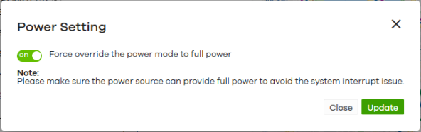 As of this writing, the following is a list of models that will show the edit icon for enabling full power mode: NAP303, NAP353, NWA1302-AC, NWA1123-AC HD, NWA5123-AC HD, WAC6303D-S, WAC6502D-E, WAC6502D-S, WAC6503D-S, WAC6552D-S, WAC6553D-S, WAX650S, NWA110AX, WAX510D. |
Antenna | This displays the antenna orientation settings for the Nebula AP that comes with internal antennas and also has an antenna switch. |
Smart mesh | This shows whether Nebula Smart Mesh is enabled on the Nebula AP. For more information about Smart Mesh, see Nebula Smart Mesh. To view the list of Nebula APs that support smart mesh, go to Help > Device function table. |
Edit | Edit the Nebula AP’s Smart Mesh settings. 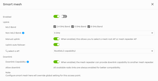 |
Enabled | Enable or disable Smart Mesh on the Nebula AP. This setting overrides the Smart Mesh settings configured for the Nebula AP’s site in NCC. |
Lock | When enabled, the Nebula AP’s local Smart Mesh settings overrides the Smart Mesh settings configured for the Nebula AP’s site in NCC. Example 1: If Smart Mesh is enabled for the site in NCC, you can disable Smart Mesh on the Nebula AP by setting Lock to on and Enabled to off. Example 2: If Smart Mesh is disabled for the site in NCC, you can enable Smart Mesh on the Nebula AP by setting Lock to on and Enabled to on. |
Uplink Downlink | Select MLO (Multi-Link Operation) to allow a WiFi7 client to connect to the WiFi7 Nebula AP using multiple frequency bands simultaneously. This increases speed and improves reliability of the WiFi connection. MLO makes WiFi7 ideal for streaming 4K / 8K videos, using augmented reality (AR), virtual reality (VR) applications and playing online games. You need to select at least 2 frequency bands for MLO to work. |
Band (for non MLO models) / MLO Band (for MLO models) | This setting will apply to mesh extender. • Select 2.4 GHz to use the 2.4 GHz band for regular Internet surfing and downloading. • Select 5 GHz or 6 GHz to use the 5 or 6 GHz band for time sensitive traffic like high-definition video, music, and gaming. 6 GHz will display only for mesh extender that support it. |
Non MLO Band | This setting will apply to mesh extender. Select Auto (high band preferred) to allow the mesh extender to select a higher radio band mesh controller. |
Manual uplink | When enabled, this allows you to select a mesh controller or mesh extender. |
Uplink auto failover | When enabled, an mesh extender that cannot connect to the selected mesh controller after 5 tries, will automatically connect to another mesh controller or mesh extender. |
select an AP | Select a mesh controller or mesh extender. |
Downlink capability | When enabled, the mesh extender can provide downlink capability to another mesh extender. |
Allow downlink | All available radio links are always enabled for better compatibility. |
Wireless bridge | This shows whether wireless bridge is enabled on the Nebula AP. For more information about wireless bridge, see Wireless Bridge. 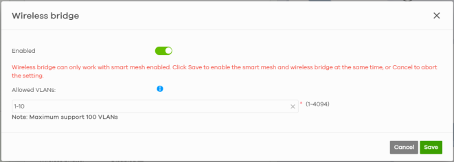 Wireless bridge can only work when smart mesh is enabled in this screen. |
Edit | Edit the Nebula AP’s wireless bridge settings. |
Enabled | Enable or disable wireless bridge on the Nebula AP. If Smart Mesh is disabled for the site in NCC, then enabling wireless bridge automatically enables Smart Mesh on the Nebula AP. |
Allowed VLANs | Enter the IDs of the VLANs that the Nebula AP will forward over the wireless bridge. By default, this field uses the VLANs allowed for LAN1 at Site-wide > Configure > Access points > AP & port settings. For details, see AP & Port Settings. |
History | Click Event log to go to the Site-wide > Monitor > Access points > Event log screen. |
Configuration status | This shows whether the configuration on the Nebula AP is up-to-date. |
Firmware availability | This shows whether the firmware on the Nebula AP is up-to-date or there is firmware update available for the Nebula AP. Click the link to go Site-wide > Configure > Firmware management. Select the Nebula AP and click Upgrade now. On the confirmation screen click Ok to install the latest (default) or stable firmware for the Nebula AP. |
Current version | This shows the firmware version currently installed on the Nebula AP. |
Uptime | This shows how long the Nebula AP has been running since it last restarted or was turned on. |
Maintenance | This shows whether automatic reboot is scheduled on the Nebula AP. |
Edit | Click the Enable the schedule switch to the right to have the Nebula AP restart at a specific time on selected days of the week. By scheduling a reboot, you can have the Nebula AP refresh the network connections at a specified time, allowing automatic reconnection with WiFi clients in case of a connection failure. Select the day(s) of the week to have the automatic restart. Specify the time of the day (in 24-hour format) to have the Nebula AP automatically restart. For example, 23:00 is 11:00 PM. 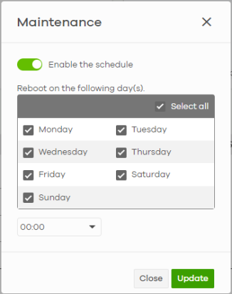 |
Map | This shows the location of the Nebula AP on Google map (Map view or Satellite imagery view) or on a floor plan. Click Floor plan to display a list of existing floor plans. Each floor plan has a drawing that shows the rooms scaled and viewed from above. Drag-and-drop your Nebula AP directly on the Google map or click Position device to update the Nebula AP’s address (physical location). 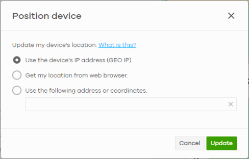 • Select GEO IP to use the public IP address of the Nebula AP. • Select Get my location from web browser to use the public IP address of the computer accessing the NCC portal. • Select Use the following address or coordinates to enter the complete address or coordinates of the Nebula AP. Nebula APs that are offline cannot use GEO IP. |
Photo | This shows the photo of the Nebula AP. Click Add to upload one or more photos. Click x to remove a photo. |
Live tools AFC Report | An outdoor Nebula AP must be able to automatically determine their geolocation (latitude/longitude), height (altitude), and serial number, and send this data through HTTPS (direct Internet connection) to the AFC system. AFC stands for Automated Frequency Coordination, a system mandated by the Federal Communications Commission (FCC) in the United States to manage spectrum sharing in the 6 GHz band (5.925 to 7.125 GHz). The AFC Report shows the EIRP (Equivalent Isotropic Radiated Power) in dBm or dBW, radiated by the Nebula Root Plus / Leaf Plus antenna that is used to determine the approved channels and power limits. |
Traffic | This shows the Nebula AP traffic statistics. |
Current stations | This shows the Nebula AP’s connected WiFi clients’ MAC address, SSID name, IPv4 Address, Signal strength, Security, Channel, Tx rate, Rx rate, Association time, and Capability. |
Ping | Enter the domain name or IP address of a computer that you want to perform ping from the Nebula AP in order to test a connection and click Ping. This can be used to determine if the Nebula AP and the computer are able to communicate with each other. |
Traceroute | Enter the domain name or IP address of a computer that you want to perform traceroute from the Nebula AP and click Run. This determines the path a packet takes to the specified computer. |
Reboot device | Click the Reboot button to restart the Nebula AP. All connected clients will be temporarily disconnected during reboot. |
Locator LED | Enter a time interval between 1 and 60 minutes. The locator LED will blink for the number of minutes set here once you turn on the locator LED. Click the  button to turn on the locator feature, which shows the actual location of the Nebula AP between several devices in the network. |
Remote SSH | This allows you to establish a remote connection to this Nebula AP by specifying the port number. Then click Establish. This feature is available to the organization owner, organization administrators with full privileges, and site administrators with full privileges. |
Wired stations | This shows the Nebula AP’s connected wired clients’ MAC address, IPv4 Address, Port number, and the VLAN ID assigned to the wired station. At the time of writing Wired stations is available for WAC500H only. |
Reprovision | To ensure that the Nebula AP running configuration is synchronized with the NCC settings, click Reprovision. The client devices connected to your Nebula AP may be temporarily disconnected. Click Yes to confirm. This feature is available: • To the organization owner, organization administrators with full or installer privileges, and site administrators with full or installer privileges • When the previous field Configuration status shows Up to date. |
Neighbor scan | This shows the Nebula AP’s neighboring AP’s BSSID, SSID Name, Channel ID, Band, 802.11 Mode, Security, and Last seen information. This allows you to monitor the WiFi signals for other wireless APs that is not under the control of NCC, and which can potentially open up holes in a network’s security. |
Access point usage and connectivity Move the cursor over the chart to see the transmission rate at a specific time. Click DL (downlink), UL (uplink), 2.4GHz, 5GHz, or 6GHz to hide or display the corresponding line on the chart below. | |
Zoom | Select to view the statistics in the past 2 hours, day, week, or month. |
Pan | Click to move backward or forward by one day or week. |
Switches
This screen allows you to view the detailed information about a Nebula Switch in the selected site. Click Site-wide > Devices > Switch to access this screen.
Site-wide > Devices > Switch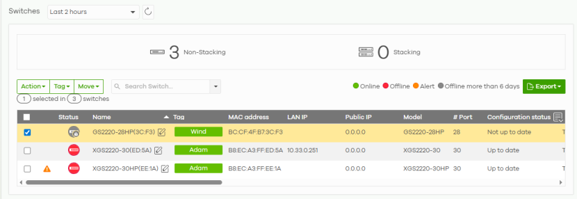
The following table describes the labels in this screen.
Label | Description |
|---|---|
Switches | Select to view the Nebula Switch information and connection status in the past two hours, day, week or month. |
 | Click this button to reload the data-related frames on this page. |
Action | Perform an action on the selected Nebula Switches. |
Reboot | Restart the Nebula Switch. |
Upgrade | Upgrade the firmware on the Nebula Switch. |
Tag | Select one or multiple Nebula Switches and click this button to create a new tag for the Nebula Switchs or delete an existing tag. |
Move | Select one or multiple Nebula Switches and click this button to move the Nebula Switch to another site or remove the Nebula Switch from the current site. |
Search | Specify your desired filter criteria to filter the list of Nebula Switches. |
Switch | This shows the number of Nebula Switches connected to the site network. |
Export | Click this button to save the Nebula Switch list as a CSV or XML file to your computer. |
Status | This shows the status of the Nebula Switch. Hover the mouse over the icon for a brief description. • Green: The Nebula Switch is online and has no alerts. • Amber: The Nebula Switch has alerts. • Red: The Nebula Switch is offline. • Gray: The Nebula Switch has been offline for 7 days or more. • With lock: The Nebula Switch is locked by Auto Configuration Recovery. See Site-wide > Configure > Switch > Switch settings for more information. Move the cursor over an amber alert icon to view the alerts the NCC generates when an error or something abnormal is detected on the IPTV network. |
Name | This shows the descriptive name of the Nebula Switch. Click the Edit icon to change the Nebula Switch name. |
Tag | This shows the user-specified tag for the Nebula Switch. |
MAC address | This shows the MAC address of the Nebula Switch. In Cloud Stacking mode, this shows the MAC address of the master Nebula Switch in the stacking system. |
LAN IP | This shows the local (LAN) IP address of the Nebula Switch. |
Public IP | This shows the global (WAN) IP address of the Nebula Switch. |
Model | This shows the model number of the Nebula Switch. |
MSP Product ID | This shows the unique product ID designated by the MSP to identify your Nebula Switch. |
# Port | This shows the number of the Nebula Switch port which is connected to the NCC. |
Configuration status | This shows whether the configuration on the Nebula Switch is up-to-date. When it shows Not up to date, require upgrade to latest firmware., click the iNote and click upgrade now. On the confirmation screen click Ok to install the latest firmware for the Nebula Switch. |
Bandwidth Utilization (Uplink port) | This shows what percentage of the upstream/downstream bandwidth is currently being used by the Nebula Switch’s uplink port. |
Production information | This shows the Nebula Switch’es product description to explain what this Nebula Switch is and also provides information about its features. |
Connectivity | This shows the Nebula Switch connection status. Nothing displays if the Nebula Switch is offline. The gray time slot indicates the connection to the NCC is down, and the green time slot indicates the connection is up. Move the cursor over a time slot to see the actual date and time when a Nebula Switch is connected or disconnected. |
Description | This shows the user-specified description for the Nebula Switch. |
Device mode | This shows Non-Stacking when the Nebula Switch is not a member of a stacking system. This shows Stacking when the Nebula Switch is a member of a stacking system. |
Serial number | This shows the serial number of the Nebula Switch. |
Firmware status | This shows whether the firmware installed on the Nebula Switch is up-to-date. |
Firmware type | This shows Stable when the installed firmware may not have the latest features but has passed Zyxel internal and external testing. This shows Latest when the installed firmware is the most recent release with the latest features, improvements, and bug fixes. This shows General Availability when the installed firmware is a release before Latest, but is newer than stable and is still undergoing Zyxel external testing. This shows Dedicated when the installed firmware is locked and Zyxel support is monitoring. Contact Zyxel customer support if you want to unlock the firmware in order to upgrade to a later one. This shows Beta when the installed firmware is a release version for testing the latest features and is still undergoing Zyxel internal and external testing. This shows N/A when the Nebula Switch is offline and its firmware status is not available. |
Firmware availability | This shows whether the firmware on the Nebula Switch is Up to date, there is firmware update available for the Nebula Switch (Upgrade available), or a specific version of firmware has been installed by Zyxel customer support (Locked). |
Current version | This shows the firmware version currently installed on the Nebula Switch. |
Usage | This shows the amount of data transmitted or received by the Nebula Switch’es clients. |
IP type | This shows whether the IP address was assigned automatically (DHCP), or manually (Static IP). |
 | Click this icon to display a greater or lesser number of configuration fields. For faster loading of data, select only the configuration fields listed that do NOT take a long time to fetch data. |
Switch Details
Click a Nebula Switch entry in the Site-wide > Devices > Switch screen to display individual Nebula Switch statistics.
Site-wide > Devices > Switch: Switch Details (Without Stacking)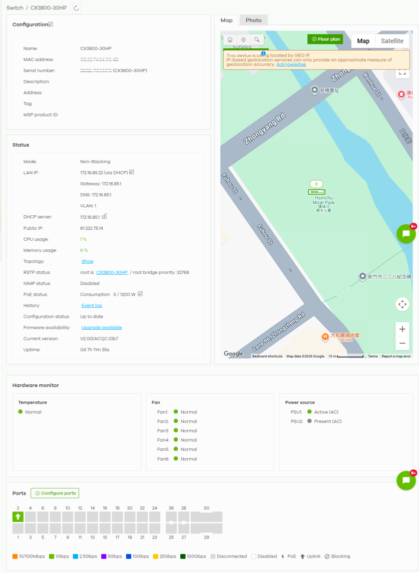
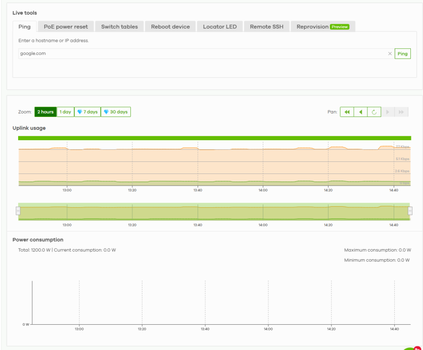
Site-wide > Devices > Switch: Switch Details (With Stacking)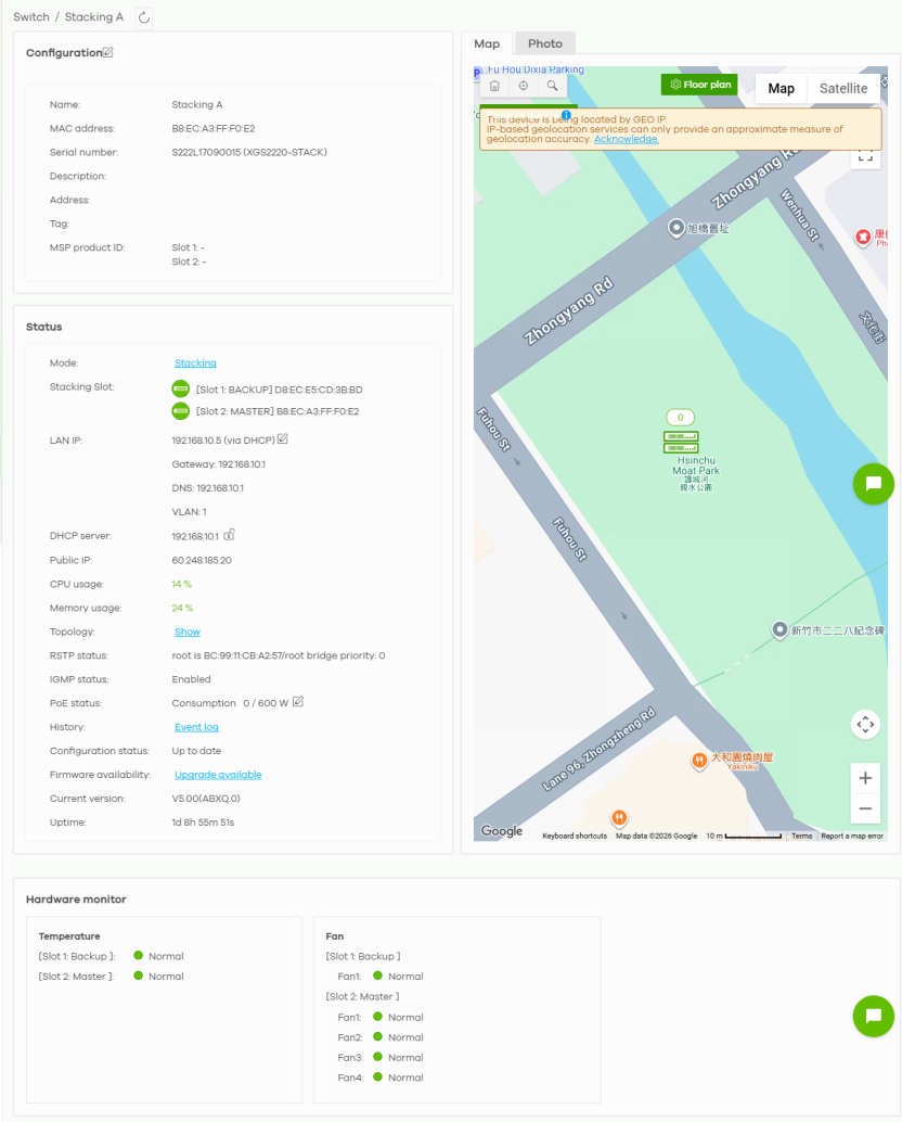
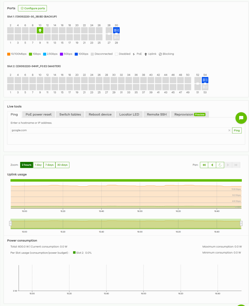 The banner This switch is currently protected by Auto Configuration Recovery will display when this Nebula Switch is locked by NCC. Click the Unlock button to continue using the Nebula Switch.
The following table describes the labels in this screen.
Label | Description |
|---|---|
 | Click this button to reload the data-related frames on this page. |
Unlock | This button only appears when the Nebula Switch is locked by NCC. Click this button to continue using the Nebula Switch. |
Configuration | Click the edit icon to change the Nebula Switch name, description, tags and address. You can also move the Nebula Switch to another site. After modifying a Nebula Switch name, the new name will be synchronized to the Nebula Switch and can be seen by protocols such as SNMP and LLDP. |
Name | This shows the descriptive name of the Nebula Switch. |
MAC address | This shows the MAC address of the Nebula Switch. In stacking mode, this shows the MAC address of the master Nebula Switch in the stacking system. |
Serial number | This shows the serial number of the Nebula Switch. |
Description | This shows the user-specified description for the Nebula Switch. |
Address | This shows the user-specified address for the Nebula Switch. |
Tag | This shows the user-specified tag for the Nebula Switch. |
MSP Product ID | This shows the unique product ID designated by the MSP to identify your Nebula Switch. You can use alphanumeric and ()+/:=?!*#@$_%- characters, and it can be up to 64 characters. |
Status Mode | This shows if the Nebula Switch is in Stacking or Non-Stacking mode. |
Stacking Slot | This shows the following information of the stacked Nebula Switch: • Slot ID, • Role of the stacked Nebula Switch; MASTER, BACKUP or LINECARD, and • MAC address. |
LAN IP | This shows the local (LAN) IP address of the Nebula Switch. It also shows the IP addresses of the gateway and DNS servers. Click Edit to open a screen where you can change the IP address, VLAN ID number and DNS server settings. 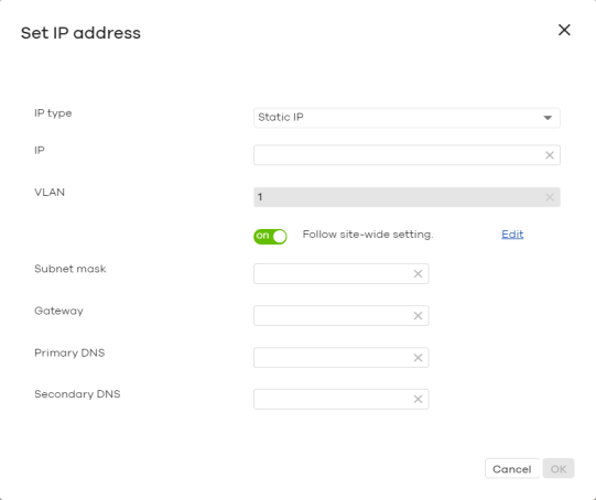 To prevent an IP address conflict, NCC will prevent input of an IP address already used by another Nebula Switch in the same site. |
DHCP server | This shows the IP address of the DHCP server. |
Public IP | This shows the global (WAN) IP address of the Nebula Switch. |
CPU usage | This shows what percentage of the Nebula Switch’s processing capability is currently being used. |
Memory usage | This shows what percentage of the Nebula Switch’s RAM is currently being used. |
Topology | |
RSTP status | This shows Disabled when RSTP is disabled on the Nebula Switch. Otherwise, it shows the name or MAC address of the Nebula Switch that is the root bridge of the spanning tree, and the bridge priority. |
IGMP status | This shows whether IGMP is enabled on the Nebula Switch. If IGMP is enabled, it also shows the ID number of the VLAN on which the Nebula Switch learns the multicast group membership and the IP address of the Nebula Switch interface in IGMP querier mode. |
PoE status | This shows the power management mode, the amount of power the Nebula Switch is currently supplying to the connected PoE-enabled devices over the total power the Nebula Switch can provide to the connected PoE-enabled devices on the PoE ports. N/A displays if the Nebula Switch does not support PoE. In Cloud Stacking mode, this shows the total amount of power all the Nebula Switches in the stacking system are currently supplying to the connected PoE-enabled devices over the total power all the Nebula Switches in the stacking system can provide to the connected PoE-enabled devices on the PoE ports. Click the edit icon to open the PoE Configuration screen. See PoE Configuration. |
History | Click Event log to go to the Site-wide > Monitor > Switch > Event log screen. |
Configuration status | This shows whether the configuration on the Nebula Switch is up-to-date. |
Firmware availability | This shows whether the firmware on the Nebula Switch is up-to-date or there is firmware update available for the Nebula Switch. When it shows Upgrade available, click the link to go Site-wide > Configure > Firmware management. Select the Nebula Device and click Upgrade now. On the confirmation screen click Ok to install the latest (default) or stable firmware for the Nebula Switch. |
Current version | This shows the firmware version currently installed on the Nebula Switch. |
Uptime | This shows how long the Nebula Switch has been running since it last restarted or was turned on. For a stacking Nebula Switch, this shows the uptime data of the master Nebula Switch. |
Map | This shows the location of the Nebula Switch on Google map (Map view or Satellite imagery view) or on a floor plan. Click Floor plan to display a list of existing floor plans. Each floor plan has a drawing that shows the rooms scaled and viewed from above. Drag-and-drop your Nebula Switch directly on the Google map or click Position device to update the Nebula Switch’es address (physical location). 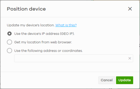 • Select GEO IP to use the public IP address of the Nebula Switch. • Select Get my location from web browser to use the public IP address of the computer accessing the NCC portal. • Select Use the following address or coordinates to enter the complete address or coordinates of the Nebula Switch. Nebula Switches that are offline cannot use GEO IP. |
Photo | This shows the photo of the Nebula Switch. Click Add to upload one or more photos. Click x to remove a photo. |
Hardware monitor | |
Temperature | The Nebula Switch has temperature sensors (BOARD / PHY / CPU/MAC) that are capable of detecting and reporting if the temperature rises above the threshold. BOARD / PHY / CPU/MAC refers to the location of the temperature sensor on the Switch printed circuit board. This field displays Normal for temperatures below the threshold and Abnormal for those above. Make sure there is at least 2 cm of clearance on the top and bottom of the Nebula Switch, and at least 5 cm of clearance on all four sides of the Nebula Switch. This allows air circulation for cooling.Do NOT block the ventilation holes on the Nebula Switch. Allow clearance for the ventilation holes to prevent your Nebula Switch from overheating. Overheating could affect the performance of your Nebula Switch, or even damage it. |
Fan | Normal indicates that this fan is functioning at the normal speed. High Speed indicates that this fan is functioning above the normal speed. When the SFP+ transceiver temperature exceeds the temperature threshold (see your transceiver documentation), the Nebula Switch automatically turns on the fans with maximum fan speed to cool down the system. The fans do not automatically turn off after the SFP+ transceiver temperature returns below threshold. To turn off the fans, you have to click Reset. Failure indicates that this fan is functioning below the minimum speed. Go to Help > Support tools > Device function table to view the supported Nebula Switches. |
Power source | When the Nebula Switch uses two power modules, one is redundant. If one power module fails (PSU1) the system can operate on the remaining module (PSU2). Active (AC) indicates that the Nebula Switch is currently operating from the AC power source to which the power module is connected. Active (DC) indicates that the Nebula Switch is currently operating from the DC power source to which the power module is connected. Active (PoE-powered BT) indicates that the Nebula Switch is currently operating from the 802.3bt 60/90 W power source. Active (PoE-powered AT) indicates that the Nebula Switch is currently operating from the 802.3at 30 W power source. Active (PoE-powered AF) indicates that the Nebula Switch is currently operating from the 802.3af 15.4 W power source. Standby indicates the redundant power module is connected to a power source, but the Nebula Switch is NOT operating from it. Present indicates the power module is connected to the Nebula Switch, but is not connected to a power source and there is no available power. Absent indicates there is no power module connected to the Nebula Switch. Error indicates that this power module is functioning below the power requirement. Or, the fan in this power module is not working. Go to Help > Support tools > Device function table to view the supported Nebula Switches. |
Ports This shows the ports on the Nebula Switch. You can click a port to see the individual port statistics. See Switch Port Details. Move the pointer over a port to see additional port information. The port color indicates the connection status of the port. • Gray (#888888): The port is disconnected. • Orange (#FF8900): The port is connected and is transmitting data at 10 or 100 Mbps. • Green (#64BE00): The port is connected and is transmitting data at 1000 Mbps (1 Gbps). • Azure (#00B2FF): The port is connected and is transmitting data at 2.5 Gbps. • Violet (#8800FF): The port is connected and is transmitting data at 5 Gbps. • Blue (#004FEE): The port is connected and is transmitting data at 10000 Mbps (10 Gbps). When the port is in the STP blocking state, failed LACP negotiation state, or failed port authentication state, a blocked icon displays on top of the port (  for example) in the diagram. | |
Configure ports | Click this button to go to the Site-wide > Configure > Switches > Switch ports screen, where you can view port summary. See Switch Ports. |
Name | This shows the Nebula Switch name configured in NCC. |
Status | This shows the connection status of the port. |
LLDP | This shows the LLDP information received on the port. |
Type | This shows the port type (Trunk or Access), PVID, and allowed VLANs. |
Speed | This shows the current connection speed of the port. If the speed is unavailable, this displays “Ethernet”. |
Power reset | This button only appears when the PoE port is connected to a PD (powered device). Follow the prompt and click Confirm to reboot the PD connected to this port. This button is not available for an uplink port. |
Live tools | |
Ping | Enter the host name or IP address of a computer that you want to perform ping in order to test a connection and click Ping. |
PoE power reset | Enter the number of, or range of PoE ports and click the Power reset button to disable and enable the PoE ports again. |
MAC table | This shows what device MAC address, belonging to what VLAN group (if any) is forwarded to which ports. You can define how it displays and arrange the data in the summary table below. This tab will appear for NSW100 and NSW200 Series only. |
Switch tables | Import the following data into NCC: • MAC table. Click Run to show what device MAC address, belonging to what VLAN group (if any) is forwarded to which ports. You can define how it displays and arrange the data in the summary table. • Routing table. Click Run to show the routing destination, gateway, interface IP addresses, hop count, and routing methods. The routing table is only displayed for L3 Nebula Switches. • ARP table. Click Run to show the IP-to-MAC address mappings. The ARP table is only displayed for L3 Nebula Switches. • IP source guard. Click Run to show the static, DHCP snooping, blocked client entries, and expiration time of DHCP snooping and blocked entries on the Nebula Switch. After clicking Run in IP source guard, the IPSG (IP source guard) table could be empty if: • It takes about 5 minutes to refresh the address table after you apply the Nebula Switch settings • Protected port is not specified • NCC may not get completed data from Nebula Switch due to unstable network. Please retry. |
Reboot device | Click the Reboot button to restart the Nebula Switch. |
Locator LED | Enter a time interval between 1 and 60 minutes to stop the locator LED from blinking. The locator LED will start to blink for the number of minutes set here. Click the  button to turn on the locator feature, which shows the actual location of the Nebula Switch between several Nebula Switches in the network. |
Remote SSH | Select to use TCP (Transmission Control Protocol) Port 22 or 443 to establish a remote connection to this Nebula Switch. The Nebula Switch will create a reverse SSH (Secure SHell) connection. Then click Establish. After clicking Ok, NCC will provide a remote connection IPv4 address and service port number. For example, Remote connection: 34.247.173.104:27086. Use this IPv4 address and port to connect to the Nebula Switch using an SSH terminal emulator (for example, PuTTY). The remote session will be available for 30 minutes. In case the connection cannot be established, confirm that the network allows Port 22 or 443. Use Remote SSH for troubleshooting only. |
Reprovision | To ensure that the Nebula Switch running configuration is synchronized with the NCC settings, click Reprovision. The client devices connected to your Nebula Switch may be temporarily disconnected. Click Yes to confirm. This feature is available: • To the organization owner, organization administrators with full or installer privileges, and site administrators with full or installer privileges • When the previous field Configuration status shows Up to date. |
Uplink usage Move the cursor over the chart to see the transmission rate at a specific time. | |
Zoom | Select to view the statistics in the past 2 hours, day, week, month, 3 months or 6 months. |
Pan | Click to move backward or forward by one day or week. |
Power Consumption | |
Total | This shows the total power the Nebula Switch can provide to the connected PoE-enabled devices on the PoE ports, over the amount of power the Nebula Switch is currently supplying to the connected PoE-enabled devices. |
Per slot usage (consumption/power budget) | In Cloud Stacking mode, this shows the current power consumption over the total power budget (in percentage) of each Nebula Switch in the stacking system. |
Maximum / Minimum consumption | This shows the current, total, maximum and minimum power consumption of the Nebula Switch. |
y-axis | The y-axis shows the amount of power used in Watts. In Cloud Stacking mode, each stacked colored graph represents the power consumption of each Nebula Switch. The highest point of the graph represents the total power consumption of the stacked Nebula Switches at the time. For example, if Nebula Switch 1 = 30 W, Nebula Switch 2 = 40 W, Nebula Switch 3 = 50 W. The highest point in Nebula Switch 2 is 70 W. The highest power consumption is 120 W at the time. |
x-axis | The x-axis shows the time period over which the power consumption is recorded. Hover the mouse over the graph to view the recorded power consumption of a Nebula Switch on a specific time.  |
PoE Configuration
Use this screen to set the PoE settings for the Nebula Switch. To access this screen, click the edit icon next to PoE Status in the Site-wide > Devices > Switch: Switch Details screen.
To set PoE settings for an individual port, such as schedule, priority, and power mode, edit the Nebula Switch’es port settings. For details, see Switch Ports.Site-wide > Devices > Switch: Switch Details: PoE Configuration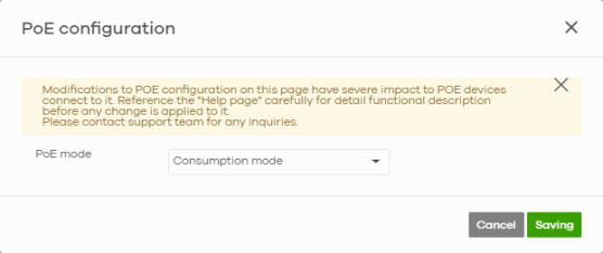
The following table describes the labels in this screen.
Label | Description |
|---|---|
PoE Mode | Select the power management mode you want the Nebula Switch to use. Classification mode – Select this if you want the Nebula Switch to reserve the Max Power (mW) to each powered device (PD) according to the priority level. If the total power supply runs out, PDs with lower priority do not get power to function. Consumption mode – Select this if you want the Nebula Switch to manage the total power supply so that each connected PD gets a resource. However, the power allocated by the Nebula Switch may be less than the Max Power (mW) of the PD. PDs with higher priority also get more power than those with lower priority levels. |
Close | Click this button to exit this screen without saving. |
Saving | Click this button to save your changes and close the screen. |
Switch Port Details
Use this to view individual Nebula Switch port statistics. To access this screen, click a port in the Ports section of the Site-wide > Devices > Switch: Switch Details screen or click the details link next to a port in the Site-wide > Configure > Switch > Switch ports screen.
Site-wide > Devices > Switch: Switch Details: Port Details 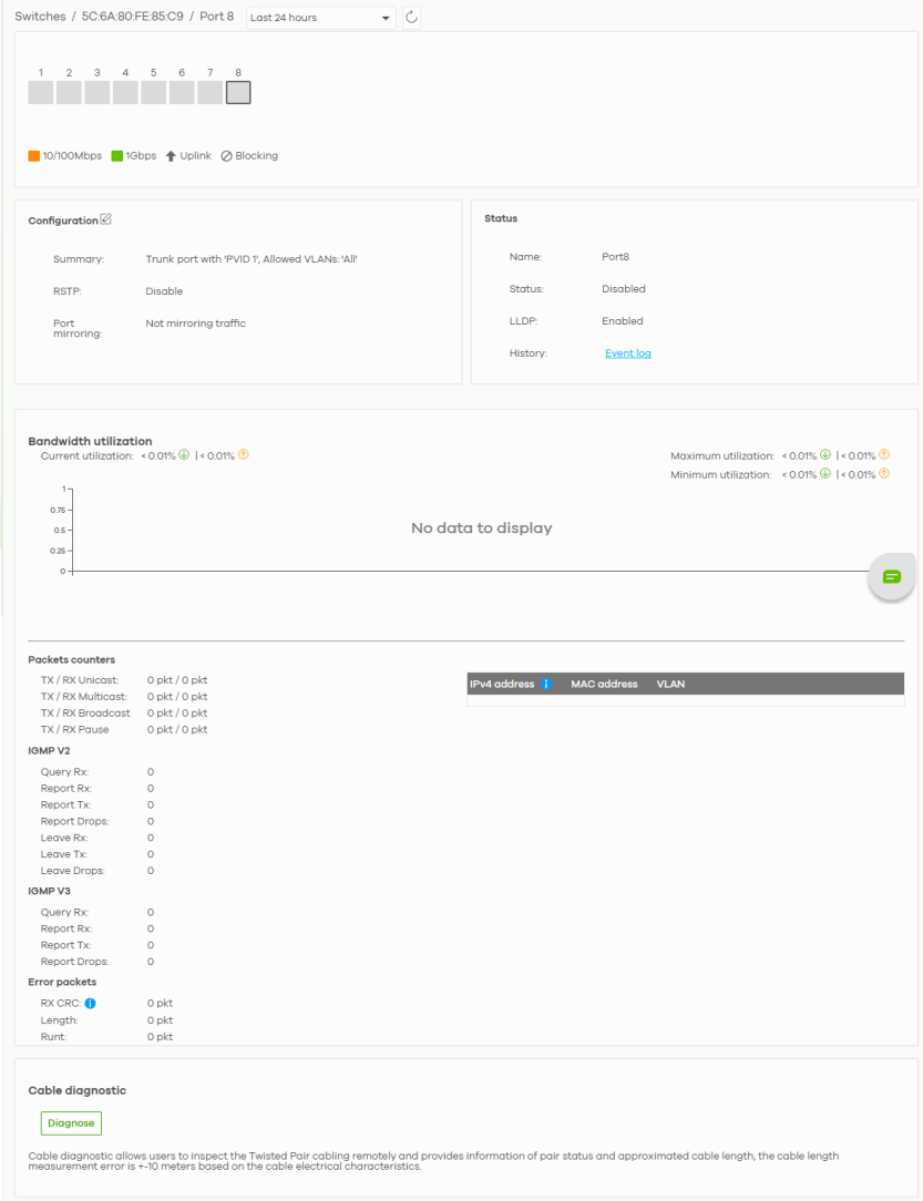
The following table describes the labels in this screen.
Label | Description |
|---|---|
 | Click this button to reload the data-related frames on this page. |
Switch / Port | Select to view the port information and connection status in the past two hours, day, week or month. |
Port | This figure shows the ports on the Nebula Switch. Click a port to go to the corresponding port details screen. The selected port is highlighted. Move the pointer over a port to see additional port information, such as its name, MAC address, type, and connection speed. The port color indicates the connection status of the port. • Gray (#888888): The port is disconnected. • Orange (#FF8900): The port is connected and is transmitting data at 10 or 100 Mbps. • Green (#64BE00): The port is connected and is transmitting data at 1000 Mbps (1 Gbps). • Azure (#00B2FF): The port is connected and is transmitting data at 2.5 Gbps. • Violet (#8800FF): The port is connected and is transmitting data at 5 Gbps. • Blue (#004FEE): The port is connected and is transmitting data at 10000 Mbps (10 Gbps). When the port is in the STP blocking state, failed LACP negotiation state, or failed port authentication state, a blocked icon displays on top of the port (  for example) in the diagram. |
Name | This shows the descriptive name of the port. |
Status | This shows the connection status of the port. |
MAC address | This shows the MAC address of the port. |
Type | This shows the port type (Trunk or Access), PVID, and allowed VLANs. |
Speed | This shows the current connection speed of the port. If the speed is unavailable, this displays “Ethernet”. |
LLDP | This shows the LLDP information received on the port. |
Configuration Click the edit icon to open the Switch ports screen and show the ports that match the filter criteria (the selected port number). See Switch Ports. | |
Summary | This shows the port’s VLAN settings. |
RSTP | This shows whether RSTP is disabled or enabled on the port. |
Port mirroring | This shows whether traffic is mirrored on the port. |
Status | |
Name | This shows the name of the port. |
Status | This shows the status of the port. |
LLDP | This shows the LLDP (Link Layer Discovery Protocol) information received on the port. |
History | Click Event log to go to the Site-wide > Monitor > Switches > Event log screen. |
Bandwidth Utilization | |
Current Utilization | This shows what percentage of the upstream/downstream bandwidth is currently being used by the port. |
Maximum Utilization | This shows the maximum upstream/downstream bandwidth utilization (in percentage). |
Minimum Utilization | This shows the minimum upstream/downstream bandwidth utilization (in percentage). |
y-axis | The y-axis represents the transmission rate in Kbps (kilobits per second). |
x-axis | The x-axis shows the time period over which the traffic flow occurred. |
Power Consumption | |
Total | This shows the total power consumption of the port. |
Current Consumption | This shows the current power consumption of the port. |
Maximum Consumption | This shows the maximum power consumption of the port. |
Minimum Consumption | This shows the minimum power consumption of the port. |
y-axis | The y-axis shows how much power is used in Watts. |
x-axis | The x-axis shows the time period over which the power consumption is recorded. |
Packets Counters | |
TX/RX Unicast | This shows the number of good unicast packets transmitted/received on the port. |
TX/RX Multicast | This shows the number of good multicast packets transmitted/received on the port. |
TX/RX Broadcast | This shows the number of good broadcast packets transmitted/received on the port. |
TX/RX Pause | This shows the number of 802.3x Pause packets transmitted/received on the port. |
IGMP V2/V3 | |
Query Rx | This shows the number of IGMP query packets received on the port. |
Report Rx | This shows the number of IGMP report packets received on the port. |
Report Tx | This shows the number of IGMP report packets transmitted on the port. |
Report Drops | This shows the number of IGMP report packets dropped on the port. |
Leave Rx | This shows the number of IGMP leave packets received on the port. |
Leave Tx | This shows the number of IGMP leave packets transmitted on the port. |
Leave Drops | This shows the number of IGMP leave packets dropped on the port. |
Error Packets | |
RX CRC | This shows the number of packets received with CRC (Cyclic Redundant Check) errors. CRC errors indicate packet errors in the network, potentially caused by mismatching Ethernet speed/duplex, bad cables or transceivers, or malfunctioning client devices. |
Length | This shows the number of packets received with a length that was out of range. |
Runt | This shows the number of packets received that were too short (shorter than 64 octets), including the ones with CRC errors. |
IPv4 Address | This shows the IP address of the incoming frame which is forwarded on the port. The IP address is obtained using one of the following three methods:• LLDP remote information • Information collected by the Nebula Security Gateway (NSG) in this site • Information collected by NCC when the client connected to Nebula |
MAC Address | This shows the MAC address of the incoming frame which is forwarded on the port. |
VLAN | This shows the VLAN group to which the incoming frame belongs. |
Cable Diagnostics | |
Diagnose | Click Diagnose to perform a physical wire-pair test of the Ethernet connections on the port. The following fields display when you diagnose a port. |
Channel | An Ethernet cable usually has four pairs of wires. A 10BASE-T or 100BASE-TX port only use and test two pairs, while a 1000BASE-T port requires all four pairs. This displays the descriptive name of the wire-pair in the cable. |
Pair Status | OK: The physical connection between the wire-pair is okay. Open: There is no physical connection (an open circuit detected) between the wire-pair. Short: There is a short circuit detected between the wire-pair. Unknown: The Nebula Switch failed to run cable diagnostics on the cable connected to this port. Unsupported: The port is a fiber port or it is not active. |
Cable Length | This displays the total length of the Ethernet cable that is connected to the port when the Pair Status is OK and the Nebula Switch chipset supports this feature. This shows N/A if the Pair Status is Open or Short. Check the Distance to fault. This shows Unsupported if the Nebula Switch chipset does not support to show the cable length. |
Distance to fault (m) | This displays the distance between the port and the location where the cable is open or shorted. This shows N/A if the Pair Status is OK. This shows Unsupported if the Nebula Switch chipset does not support to show the distance. |
DDMI | This section is available only on an SFP (Small Form Factor Pluggable) port. |
DDMI | Click DDMI (Digital Diagnostics Monitoring Interface) to display real-time SFP transceiver information and operating parameters on the port. You can also see the alarm and warning thresholds for temperature, voltage, transmission bias, transmission and receiving power. |
Port | This shows the number of the port on the Nebula Switch. |
Vendor | This shows the vendor name of the transceiver installed in the port. |
PN | This shows the part number of the transceiver installed in the port. |
SN | This shows the serial number of the transceiver installed in the port. |
Revision | This shows the firmware version of the transceiver installed in the port. |
Date-code | This shows the date the installed transceiver’s firmware was created. |
Transceiver | This shows the type and the Gigabit Ethernet standard supported by the transceiver installed in the port. |
Calibration | This shows whether the diagnostic information is internally calibrated or externally calibrated. |
Current | This shows the current operating parameters on the port, such as transceiver temperature, laser bias current, transmitted optical power, received optical power and transceiver supply voltage. |
High Alarm Threshold | This shows the high alarm threshold for temperature, voltage, transmission bias, transmission and receiving power. A trap is sent when the operating parameter is above the threshold. |
High Warn Threshold | This shows the high warning threshold for temperature, voltage, transmission bias, transmission and receiving power. |
Low Warn Threshold | This shows the low alarm threshold for temperature, voltage, transmission bias, transmission and receiving power. A trap is sent when the operating parameter is below the threshold. |
Low Alarm Threshold | This shows the low warning threshold for temperature, voltage, transmission bias, transmission and receiving power. |
Security Router
This screen allows you to view the detailed information about the Nebula Security Router in the selected site. Click Site-wide > Devices > Security router to access this screen.
Site-wide > Devices > Security router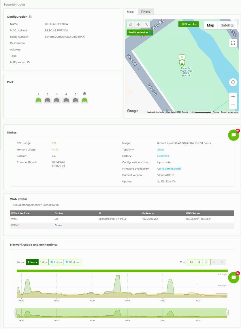
The following table describes the labels in this screen.
Label | Description |
|---|---|
Configuration Click the edit icon to change the Nebula Security Router name, description, tags and address (physical location). You can also move the Nebula Security Router to another site or remove. | |
Name | This shows the descriptive name of the Nebula Security Router. Click the Edit icon to change the Nebula Security Router name. |
MAC address | This shows the MAC address of the Nebula Security Router’s WAN port. |
Serial number | This shows the serial number of the Nebula Security Router. |
Description | This shows the user-specified description for the Nebula Security Router. |
Address | This shows the user-specified address (physical location) for the Nebula Security Router. |
Tags | This shows the user-specified tags for the Nebula Security Router. |
MSP Product ID | Enter the unique product ID designated by the MSP to identify your Nebula Security Router. You can use alphanumeric and ()+/:=?!*#@$_%- characters, and it can be up to 64 characters. |
Port | This shows the ports on the Nebula Security Router. The port is highlighted in green color when it is connected and the link is up. Move the pointer over a port to see additional port information, such as its name, connection status, MAC address, and connection speed. |
Map | This shows the location of the Nebula Security Router on Google Maps (Map view or Satellite imagery view) or on a floor plan. Click Floor plan to display a list of existing floor plans. Each floor plan has a drawing that shows the rooms scaled and viewed from above. Drag-and-drop your Nebula Security Router directly on the Google map or click Position device to update the Nebula Security Router’s address (physical location). 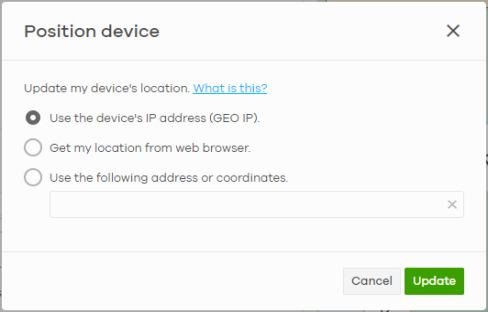 • Select GEO IP to use the public IP address of the Nebula Security Router. • Select Get my location from web browser to use the public IP address of the computer accessing the NCC portal. • Select Use the following address or coordinates to enter the complete address or coordinates of the Nebula Security Router. Nebula Security Routers that are offline cannot use GEO IP. |
Photo | This shows the photo of the Nebula Security Router. Click Add to upload one or more photos. Click x to remove a photo. |
Status | |
WAN | This shows the global (WAN) IPv4 address of the Nebula Security Router, and whether it was assigned automatically (DHCP), manually (Static IP), or by PPPoE. |
Public IP | This shows the public IP address of the site’s Security Appliance. |
CPU usage | This shows the percentage of the Nebula Security Router’s processing capability that is currently being used. |
Memory usage | This shows the percentage of the Nebula Security Router’s RAM processing capability that is currently being used. |
Session | This shows how many sessions the Nebula Security Router currently has. A session is a unique established connection that passes through, from, to, or within the Nebula Security Router. |
Channel (Band) | This shows the channel ID and WiFi frequency band currently being used by the Nebula Security Router. This field only appears for ZyWALL ATP100W, USG FLEX 100W, USG20W-VPN, and USG LITE 60AX. |
Usage | This shows the amount of data that has been transmitted or received by the Nebula Security Router’s clients. |
Topology | |
History | Click Event log to go to the Site-wide > Monitor > Security router > Event log screen. |
Configuration status | This shows whether the configuration on the Nebula Security Router is Up-to-date. When it shows Not up to date, require upgrade to latest firmware., click the iNote and click upgrade now. On the confirmation screen click Ok to install the latest firmware for the Nebula Security Router. |
Firmware availability | This shows whether the firmware installed on the Nebula Security Router is Up-to-date. When it shows Upgrade available, click the link to go Site-wide > Configure > Firmware management. Select the Nebula Security Router and click Upgrade now. On the confirmation screen click Ok to install the latest (default) or stable firmware for the Nebula Security Router. |
Current version | This shows the firmware version currently installed on the Nebula Security Router. |
Uptime | This shows how long the Nebula Security Router has been running since it last restarted or was turned on. |
WAN status | |
WAN interface | This shows the name of the WAN interface (WAN or WAN2). |
Status | This shows whether the WAN interface is online (Up) or offline (Down). |
IP | The shows the public IPv4 address and WAN IPv4 address of the interface and whether the IPv4 address was assigned automatically (DHCP) or manually (STATIC_IP). |
Gateway | This shows the IPv4 address of the gateway that helps forward this route’s traffic. |
DNS Server | This shows the currently configured DNS server IPv4 address of the WAN interface. |
Network usage and connectivity | Move the cursor over the chart to see the transmission rate at a specific time. |
Zoom | Select to view the statistics in the past 2 hours, 1 day, 7 days, or 30 days. |
Pan | Click to move backward or forward by one day or week. |
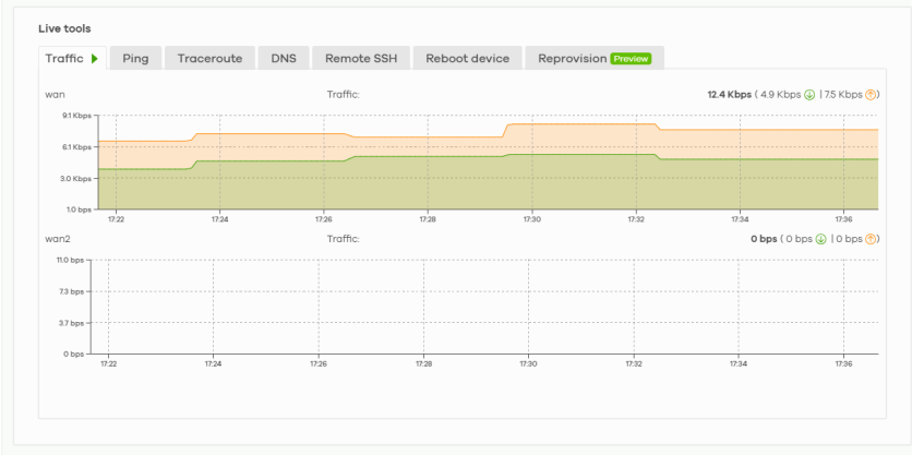
Live tools | |
Traffic | This shows the Nebula Security Router traffic statistics. |
Ping | Enter the host name or IP address of a computer that you want to perform ping in order to test a connection and click Ping. You can select the interface (Auto, WAN, WAN2, LAN, or VLAN) through which the USG FLEX sends queries for ping. • To ping for VPN/routing issues, it is not necessary to connect an end-device on the LAN interface of the Nebula Security Router. • A routing problem is possible if the WAN interface can reach the Internet but not the LAN interface. |
Traceroute | Enter the host name or IP address of a computer that you want to perform the traceroute function and click Run. You can select the interface (Auto, WAN, WAN2, LAN, or VLAN). This determines the path a packet takes to the specified computer. |
DNS lookup | Enter a host name and click Run to resolve the IP address for the specified domain name. |
Remote SSH | This allows you to establish a remote connection to this Nebula Security Router by specifying the port number. Then click Establish. This feature is available to the organization owner, organization administrators with full privileges, and site administrators with full privileges. |
Reboot device | Click the Reboot button to restart the Nebula Security Router. |
Reprovision | To ensure that the Nebula Security Router running configuration is synchronized with the NCC settings, click Reprovision. The client devices connected to your Nebula Security Router may be temporarily disconnected. Click Yes to confirm. This feature is available: • To the organization owner, organization administrators with full or installer privileges, and site administrators with full or installer privileges • When the previous field Configuration status shows Up to date. |
Firewall
This screen allows you to view the detailed information about the Nebula Security Router in the selected site. Click Site-wide > Devices > Firewall to access this screen.
Site-wide > Devices > Firewall (Cloud Mode)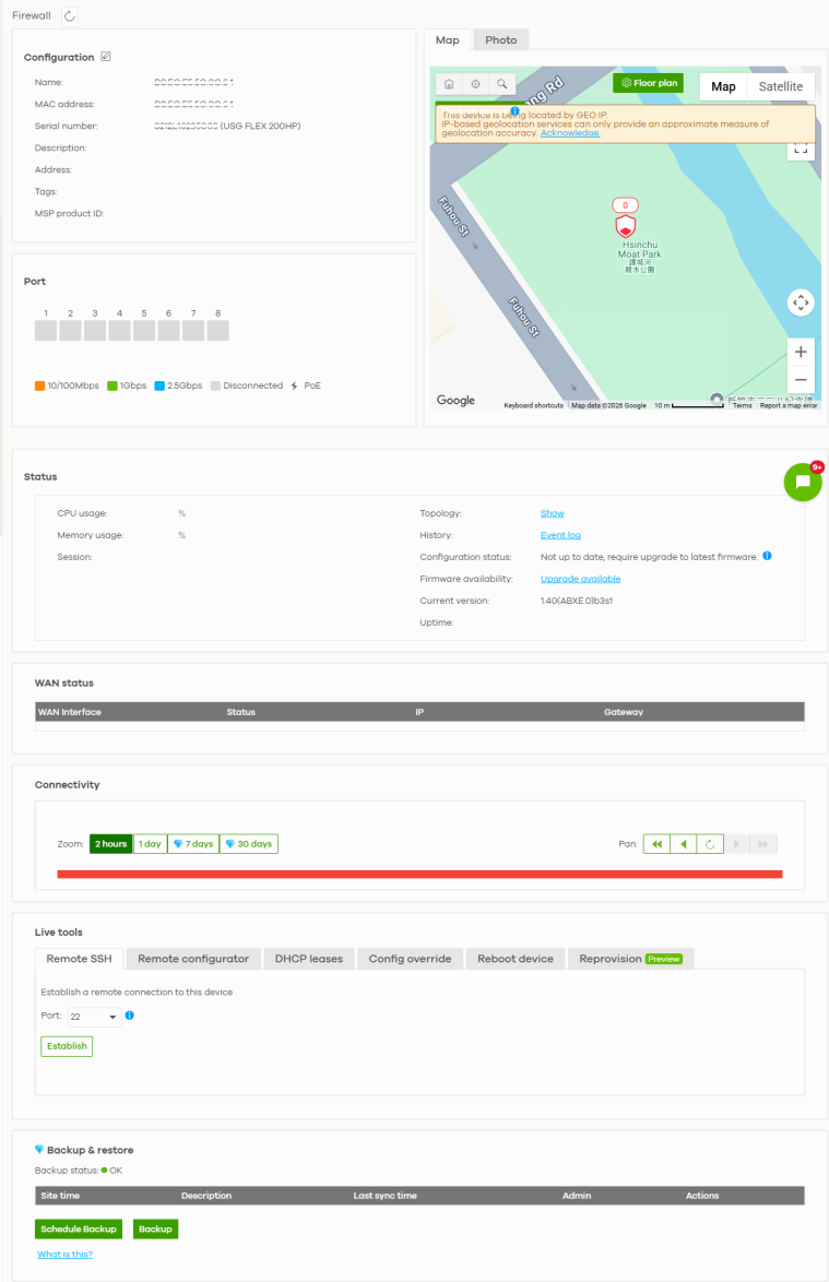
Site-wide > Devices > Firewall (Cloud Monitoring Mode)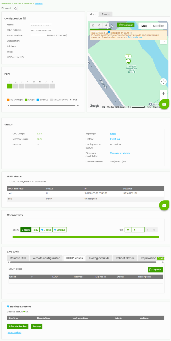
The following table describes the labels in this screen.
Label | Description |
|---|---|
Configuration Click the edit icon to change the Nebula Security Router name, description, tags and address (physical location). You can also move the Nebula Security Router to another site or remove. | |
Name | This shows the descriptive name of the Nebula Security Router. Click the Edit icon to change the Nebula Security Router name. |
MAC address | This shows the MAC address of the Nebula Security Router’s WAN port. |
Serial number | This shows the serial number of the Nebula Security Router. |
Description | This shows the user-specified description for the Nebula Security Router. |
Address | This shows the user-specified address (physical location) for the Nebula Security Router. |
Tags | This shows the user-specified tags for the Nebula Security Router. |
MSP Product ID | This shows the unique product ID designated by the MSP to identify your Nebula Security Router. You can use alphanumeric and ()+/:=?!*#@$_%- characters, and it can be up to 64 characters. |
Port | This shows the ports on the Nebula Security Router. The port is highlighted in green color when it is connected and the link is up. Move the pointer over a port to see additional port information, such as its name, connection status, MAC address, and connection speed. These fields will not show in Cloud Monitoring mode. |
Port | This shows the identity number of the selected port. |
Port Group | This shows the name of the port group that the port belongs to. |
Status | This shows the connection status of the port. |
Map | This shows the location of the Nebula Security Router on Google Maps (Map view or Satellite imagery view) or on a floor plan. Click Floor plan to display a list of existing floor plans. Each floor plan has a drawing that shows the rooms scaled and viewed from above. Drag-and-drop your Nebula Security Router directly on the Google map or click Position device to update the Nebula Security Router’s address (physical location). 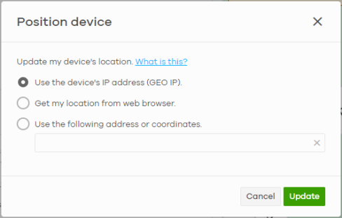 • Select GEO IP to use the public IP address of the Nebula Security Router. • Select Get my location from web browser to use the public IP address of the computer accessing the NCC portal. • Select Use the following address or coordinates to enter the complete address or coordinates of the Nebula Security Router. Nebula Security Routers that are offline cannot use GEO IP. |
Photo | This shows the photo of the Nebula Security Router. Click Add to upload one or more photos. Click x to remove a photo. |
Status These fields will not show in Cloud Monitoring mode. | |
CPU usage | This shows what percentage of the Nebula Security Router’s processing capability is currently being used. |
Memory usage | This shows what percentage of the Nebula Security Router’s RAM is currently being used. |
Session | This shows how many sessions the Nebula Security Router currently has. A session is a unique established connection that passes through, from, to, or within the Nebula Security Router. |
Channel (Band) | This shows the channel ID and WiFi frequency band currently being used by the Nebula Security Router. This field only appears for ZyWALL ATP100W, USG FLEX 100W, and USG20W-VPN. |
Usage | This shows the amount of data that has been transmitted or received by the Nebula Security Router’s clients. |
Topology | |
History | Click Event log to go to the Site-wide > Monitor > Firewall > Event log screen. |
Configuration status | This shows whether the configuration on the Nebula Security Router is Up-to-date. When it shows Not up to date, require upgrade to latest firmware., click the iNote and click upgrade now. On the confirmation screen click Ok to install the latest firmware for the Nebula Security Router. |
Firmware availability | This shows whether the firmware installed on the Nebula Security Router is Up-to-date. When it shows Upgrade available, click the link to go Site-wide > Configure > Firmware management. Select the Nebula Security Router and click Upgrade now. On the confirmation screen click Ok to install the latest (default) or stable firmware for the Nebula Security Router. |
Current version | This shows the firmware version currently installed on the Nebula Security Router. |
Uptime | This shows how long the Nebula Security Router has been running since it last restarted or was turned on. |
WAN status | |
WAN Interface | This shows the descriptive name of the active WAN connection. |
Status | This shows the connection status of the WAN interface (up or down). |
IP | This shows the IP address of the WAN interface, and whether it was assigned automatically (DHCP), manually (Static IP), or by PPPoE. |
Gateway | This shows the IP address of the default Nebula Security Router assigned to the WAN interface. |
DNS Server | This shows the IP addresses of the DNS servers assigned to the WAN interface. |
Connectivity Move the cursor over the chart to see the transmission rate at a specific time. | |
Zoom | Select to view the statistics in the past 2 hours, 24 hours, 7 days, or 30 days. |
Pan | Click to move backward or forward by one day or week. |
Live tools Traffic, Ping, Traceroute and DNS lookup, will not show in Cloud Monitoring mode. | |
Traffic | This shows the WAN port statistics. The y-axis represents the transmission rate for uploads and downloads. The x-axis shows the time period over which the traffic flow occurred. |
Ping | Enter the host name or IP address of a computer that you want to perform ping in order to test a connection and click Ping. You can select the interface (WAN, LAN, or VLAN) through which the USG FLEX sends queries for ping. • To ping for VPN/routing issues, it is not necessary to connect an end-device on the LAN interface of the Nebula Security Router. • A routing problem is possible if the WAN interface can reach the Internet but not the LAN interface. |
Traceroute | Enter the host name or IP address of a computer that you want to perform the traceroute function. This determines the path a packet takes to the specified computer. |
DNS lookup | Enter a host name and click Run to resolve the IP address for the specified domain name. |
Remote SSH | This option is available only for the Nebula Security Router owner. Establish a remote command line interface (CLI) connection to the Nebula Security Router by specifying the Port number and clicking Establish. |
Remote configurator | Click Establish to use TCP (Transmission Control Protocol) port 443 to establish a remote connection to this Nebula Security Router. The Nebula Security Router will create a reverse SSH (Secure SHell) connection. After clicking Ok, NCC will provide a remote connection IPv4 address and service port number. For example, https://63.35.218.205:31479. Use this IPv4 address and port to connect to the Nebula Security Router to open the Web Configurator. The remote session will be available for 30 minutes. In case the connection cannot be established, confirm that the network allows Port 443. Remote configurator will only show in Cloud Monitoring mode. |
DHCP leases | This shows DHCP client lease information as follows. • Client: The client's hostname. • IP: The IP addresses currently assigned to DHCP client. • MAC: The client's MAC address. • Interface: The interface to which the client is connected. • Expires in: The date and time when the IP address assigned to the client will expire. • Status: The client's DHCP assignment status. Reserved indicates that the DHCP server always assigns the same IP address to the client with this MAC address. • Description: A brief description of the DHCP lease event. For example, a MAC address is reserved for the client. |
Config override | Click Config override to apply the current Nebula Security Router Web Configurator setting to NCC. You will be prompted to copy and enter your Nebula Security Router’s serial number shown on screen and click Confirm. The Confirm button is not clickable until you enter the correct serial number. 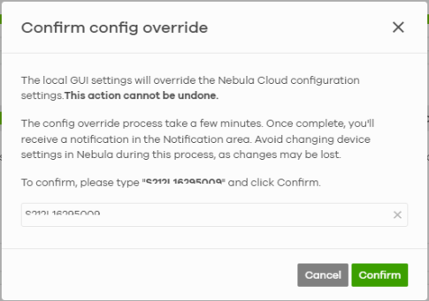 This action cannot be undone. |
Reboot device | Click the Reboot button to restart the Nebula Security Router. |
Reprovision | To ensure that the Nebula Security Router running configuration is synchronized with the NCC settings, click Reprovision. The client devices connected to your Nebula Security Router may be temporarily disconnected. Click Yes to confirm. This feature is available: • To the organization owner, organization administrators with full or installer privileges, and site administrators with full or installer privileges • When the previous field Configuration status shows Up to date. |
Backup & Restore These fields will only show in Cloud Monitoring mode. | |
Site time | This shows the date and time of the site, to which the change was applied, when the log was recorded. |
Description | This shows the description of the backup. |
Last sync time | This shows the year-month-date hour:minute:second when NCC checked the Nebula Security Router, but skip the scheduled backup because there is no configuration change. |
Admin | This shows the name of the administrator who made the back up or Schedule backup. |
Actions | Click the Restore icon to restore a previously saved configuration file from NCC to the Nebula Security Router. Click the Download icon to download the configuration file to your computer or laptop. Click the Delete icon to remove the configuration file on the Nebula Security Router. |
Schedule Backup | Select a Monthly, Weekly, or Daily backup of the current configuration of the Nebula Security Router to the NCC. Then select the Day of the month/week. Otherwise, select Disable. Then click Confirm. • NCC will skip the scheduled backup when there is no configuration change. • NCC can retain up to 10 backup configurations per Nebula Security Router in this screen. When the maximum number of backup configuration per Nebula Security Router is reached, a new backup configuration automatically overwrites an existing backup configuration, starting with the oldest existing backup configuration first. |
Backup | Click this button to create a new backup of the current configuration of the Nebula Security Router to the NCC. |
Security Gateway
This screen allows you to view the detailed information about a Nebula Security Gateway in the selected site. Click Site-wide > Devices > Security gateway to access this screen.
Site-wide > Devices > Security gateway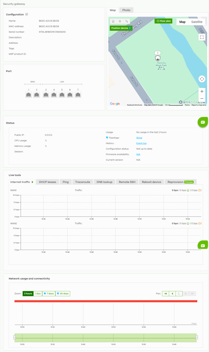
The following table describes the labels in this screen.
Label | Description |
|---|---|
Configuration Click the edit icon to change the Nebula Security Gateway name, description, tags and address. You can also move the Nebula Security Gateway to another site or remove. | |
Name | This shows the descriptive name of the Nebula Security Gateway. Click the Edit icon to change the Nebula Security Gateway name. |
MAC address | This shows the MAC address of the Nebula Security Gateway. |
Serial number | This shows the serial number of the Nebula Security Gateway. |
Description | This shows the user-specified description for the Nebula Security Gateway. |
Address | This shows the user-specified address for the Nebula Security Gateway. |
Tags | This shows the user-specified tag for the Nebula Security Gateway. |
MSP Product ID | This shows the unique product ID designated by the MSP to identify your Nebula Security Gateway. You can use alphanumeric and ()+/:=?!*#@$_%- characters, and it can be up to 64 characters. |
Port | This shows the ports on the Nebula Security Gateway. The port is highlighted in green color when it is connected and the link is up. Move the pointer over a port to see additional port information, such as its name, connection status, MAC address, and connection speed. |
Name | This shows the descriptive name of the port. |
Status | This shows the connection status of the port. |
MAC address | This shows the MAC address of the port. |
LLDP | This shows the LLDP information received on the port. |
Speed | This shows the current connection speed of the port. If the speed is unavailable, this displays “Ethernet”. |
Map | This shows the location of the Nebula Security Gateway on the Google map (Map view or Satellite imagery view) or on a floor plan. Click Floor plan to display a list of existing floor plans. Each floor plan has a drawing that shows the rooms scaled and viewed from above. Drag-and-drop your Nebula Security Gateway directly on the Google map or click Position device to update the Nebula Security Gateway’s address (physical location). 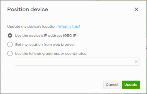 • Select GEO IP to use the public IP address of the Nebula Security Gateway. • Select Get my location from web browser to use the public IP address of the computer accessing the NCC portal. • Select Use the following address or coordinates to enter the complete address or coordinates of the Nebula Security Gateway. Nebula Security Gateways that are offline cannot use GEO IP. |
Photo | This shows the photo of the Nebula Security Gateway. Click Add to upload one or more photos. Click x to remove a photo. |
Status | |
WAN1/WAN2 | This shows the IP address, gateway, DNS, and VLAN ID information for the active WAN connection. |
Public IP | This shows the global (WAN) IP address of the Nebula Security Gateway. |
CPU usage | This shows what percentage of the Nebula Security Gateway’s processing capability is currently being used. |
Memory usage | This shows what percentage of the Nebula Security Gateway’s RAM is currently being used. |
Security Service | This shows whether Nebula Security Services (NSS) are enabled on the Nebula Security Gateway. Click What is this? to view the type of enabled security services. When the gateway’s NSS license expires, NSS is automatically disabled. This field displays an edit button which you can use to re-enable the services after renewing the NSS license. |
Session | |
Usage | This shows the amount of data that has been transmitted or received by the Nebula Security Gateway’s clients. |
Topology | |
History | Click Event log to go to the Site-wide > Monitor > Security gateway > Event log screen. |
Configuration status | This shows whether the configuration on the Nebula Security Gateway is up-to-date. When it shows Not up to date, require upgrade to latest firmware., click the iNote and click upgrade now. On the confirmation screen click Ok to install the latest firmware for the Nebula Security Gateway. |
Firmware availability | This shows whether the firmware installed on the Nebula Security Gateway is up-to-date. When it shows Upgrade available, click the link to go Site-wide > Configure > Firmware management. Select the Nebula Security Gateway and click Upgrade now. On the confirmation screen click Ok to install the latest (default) or stable firmware for the Nebula Security Gateway. |
Current version | This shows the firmware version currently installed on the Nebula Security Gateway. |
Live tools | |
Internet traffic | This shows the WAN port statistics. The y-axis represents the transmission rate in Kbps (kilobits per second). The x-axis shows the time period over which the traffic flow occurred. |
DHCP leases | This shows the IP addresses currently assigned to DHCP clients. |
Ping | Enter the host name or IP address of a computer that you want to perform ping in order to test a connection and click Ping. You can select the interface through which the Nebula Security Gateway sends queries for ping. |
Traceroute | Enter the host name or IP address of a computer that you want to perform the traceroute function. This determines the path a packet takes to the specified computer. |
DNS lookup | Enter a host name and click Run to resolve the IP address for the specified domain name. |
Remote SSH | This option is available only for the Nebula Security Gateway owner. Establish a remote connection by specifying the Port number and clicking Establish. |
Reboot device | Click the Reboot button to restart the Nebula Security Gateway. |
Reprovision | To ensure that the Nebula Security Gateway running configuration is synchronized with the NCC settings, click Reprovision. The client devices connected to your Nebula Security Gateway may be temporarily disconnected. Click Yes to confirm. This feature is available: • To the organization owner, organization administrators with full or installer privileges, and site administrators with full or installer privileges • When the previous field Configuration status shows Up to date. |
Network usage and connectivity Move the cursor over the chart to see the transmission rate at a specific time. | |
Zoom | Select to view the statistics in the past 2 hours, day, week, or month. |
Pan | Click to move backward or forward by one day or week. |
Broadband Router
This screen allows you to view the detailed information about a Nebula Broadband Router in the selected site. Click Site-wide > Devices > Broadband router to access this screen. See the Broadband Routers chapter for more information.
Accessory
This screen allows you to view the detailed information about a Nebula Accessory in the selected site. Click Site-wide > Devices > Accessory to access this screen. See the Accessory chapter for more information.